Don't like the adverts?  Click here to remove them

Diffs and lockers... just checking

knicko

Member
Joined
Dec 23, 2012
Messages
126
Country Flag
uk
I have spent time going through the forum searches and service manuals, in prep for checking over my diffs to ensure all is working as it should.

My vehicle is a 5 speed auto 100 series, so has independent front suspension and therefore no front diff lock. It obviously has a centre diff lock (CDL) in the transfer box (TB) and a rear diff lock (RDL) on the rear axle (mine doesn't engage at the moment and needs checking as per the numerous posts on this subject).

As I can't easily find somewhere with a soft surface to drive round in circles trying to engage/disengage everything, I want to jack wheels off the ground and systematically check the various functions. To check I have understood this correctly, am I right in saying:

With vehicle in High ratio, autobox in Neutral and CDL off (ie. centre diff open)...

1. raise just one (front or back) wheel and it should spin by hand as ALL drive through TB is going to that axle and then to that slipping wheel?
2. raise both wheels on the same axle and ALL drive from TB goes to that raised axle, so both it's wheels can spin by hand although they will go in opposite directions because the diff on that axle is still 'open' too?

Now if I lock the CDL, the front and rear axles are locked together, so...

3. if I raise one any one (front or back) wheel, it will NOT turn by hand as the wheels on the opposite (front or back) axle are grounded and therefore lock up both the axles?
4. This effectively tells me that the CDL is engaged and working properly?

So if I then want to check the RDL function...

5. I will need both back wheels off ground and at least one front wheel off ground, because RDL will only work with Low ratio, which automatically engages the CDL and therefore I need a front wheel to slip to allow me to turn the rear wheels by hand?
6. If I can get the RDL to engage, both raised back wheels will turn together in the same direction when one is turned by hand?
7. I presume that by turning the back wheels, I will see the raised front wheel spin too, as it is locked to the rear axle via the CDL?

I'm on my own and I've only got two axle stands and one trolley jack, so trying to work out the most efficient way to check all this, but I've got a feeling I've confused myself now!!
 
Don't think that point 3 is correct.
If you lock the CDL yes the front and rear propshafts are locked together, but the diffs are still open so you can raise a front or rear wheel and it will still turn against the diff despite the opposite wheel being on the tarmac. If it worked as you suggested than why would you have a rear locker? Yes it will be stiffer to turn, but it will still turn. This is how a vehicle gets cross-axled. Lock the CDL, then put 2 opposite wheels on ice and you're stuck.
 
In terms of point 5, with the RDL locked and the CDL locked, you only need raise one rear wheel. That should NOT turn. The rear prop is locked to the front prop, the front wheels are both on tarmac and the companion rear wheel is locked via the RDl to the raised one.

On a final note, unless you have three lockers, there will always be a situation where you get no drive effectively. If you lock CDL and RDL then raise both rear wheels and one front, then turn a rear wheel, the front open diff will be the release for all of the drive fed into the transfer box. Or an an opposite put all three wheels back down then raise one front wheel (like it's on ice) and it will turn against the front diff.
 
Last edited:
Hmmm. Spent a lot of time achieving not much today!

I believe my CDL is working ok because when I jacked up one rear wheel, it span with the CDL off and locked up when I switched the CDL on.

Then I jacked up the whole rear axle and set to work on the RDL, which is evidently not working as the red RDL dash light is flashing and the back wheels spin in opposite directions when you spin one by hand, showing that the rear diff is open.

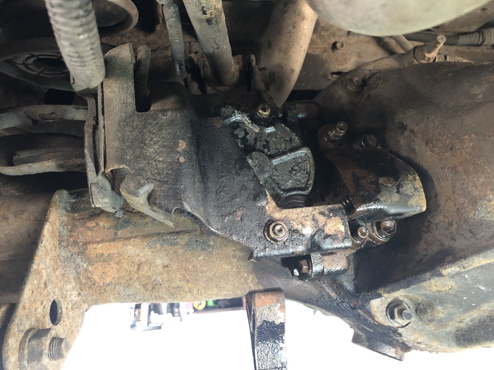
The external parts of the RDL unit didn't look too bad, The two metal guards were holding a fair bit of dried mud, which I soon brushed off once I had dismantled the guards. The top 12mm bolt of the larger guard sheared off but I'm not too concerned about it staying in place with one bolt.

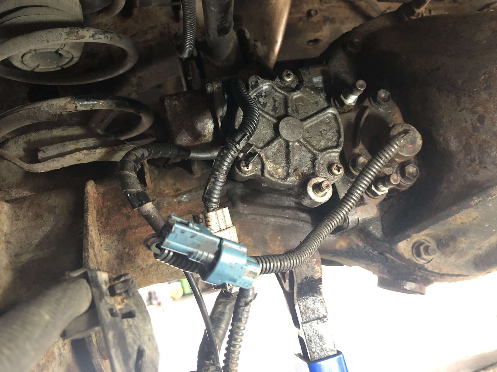
There was no sound of the actuator motor turning when the RDL switch was turned on, so I disconnected the two electrical connector blocks to make further enquiries. The larger white block appears to control the actuator, while the smaller blue block connects to a 27mm fitting that screws into the body of the unit nearest the diff. I removed this 27mm fitting and found it to be a detent ball type switch. The ball was clean, easy to spring in/out and coated in very clean looking diff oil.

While the RDL switch was in the 'on' position (and the red dash light was flashing) I put a test meter on the different terminals of the two connector blocks, with one probe to a suitable earth point on the chassis.

One of the two wires in the blue connector block was pulsing between 0 and 9V approx, which I assume was linked to the pulsing of the dash light. The other wire showed nothing.

All five wires in the white connector block showed no voltage at all. I have very little knowledge of car electrics, but I would have thought that one of the wires in this block would have been a 12v supply to power the motor, as the RDL switch was in the 'on' position?

I compressed the detent ball while it was connected to the blue block and the red RDL dash light went solid, so I guess that's working ok.

I checked the fuse diagram in the manual, which shows the 4WD system running off a 20A fuse in position 53, which is in the fusebox behind the drivers footwell panel. I pulled this fuse and it is fine (which I expected it to be as I assume it is the same fuse for the CDL too).

I then thought about removing the cover plate on the RDL actuator, to see what state it was in underneath. However the three posidrive screws were really tight and starting to round off. Then I snapped the end of the screwdriver off and at that point, thought better of continuing this line of enquiry! There didn't seem much point in risking a breakage when I still am unsure whether this is an electrical issue, rather than a mechanical one.

I've put it all back together (after spraying contact cleaner into the connector blocks) and had a look at the wiring diagram, which is linked to one of the pages on this forum. To be honest, I haven't a clue how to read it... it might as well actually be in Japanese!

Any ideas would be welcome, but I know it's probably going to mean a trip to an auto-electrician. I'll probably never need to use the RDL in anger but I do like things to work properly. I'm happy turning spanners but car electrics is all witchcraft to me, especially ECUs... God only knows what they do!

Off to buy a new screwdriver in the morning
 

Attachments

  • IMG_1605.jpg
    IMG_1605.jpg
    357.9 KB · Views: 67
  • IMG_1615.jpg
    IMG_1615.jpg
    291.1 KB · Views: 66
Last edited:
Don't like the adverts?  Click here to remove them
Forgot to say... the third 'cable' which is the one without the corrugated shroud appears in fact to be a vacuum hose, which pulled apart as I removed the metal guard. What on earth is that for?
 
It's a breather not a vacuum. Just to allow pressure to equalise when things get warmed up
 
Thanks Chris. I was just reading an older post of yours about the RDL on the 80 series, where you describe that the electrical power is only supplied to the actuator motor for a few seconds after switching on, and the actuator movement is stored in a spring pending alignment of the locker gears to allow the system to engage.
Do you know if the 100 series system works the same way? This may explain why I’m not seeing any voltage to the motor by the time I’ve climbed under the car after turning on the RDL switch?
 
You should be seeing some voltage on one pin of the plug to the RDL actuator, if unplugged, depending on what you use to measure with. If not, check the diff ECU (actually two relays with a bit of trickery in a quite small package). If it is like on the LHD cars, it is easily accessible behind the right (driver's for you) kick panel. Or it could be as simple as a missing Low Range signal, which would tell the diff-ecu not to engage the RDL.
On the plug at the RDL actuator, you have 5 connected pins. Pin 4 is ground (colour W-B), 2 (L-R) and 3 (L) are the motor. 5 (G-Y) and 6 (G) are the end stop switches inside the actuator.
2 and 3 will have ground (0 volt) on one and +12 v on the other only for the period when the end-stop for that direction is not reached, i.e. as long as there is a disagreement between the ECU order and the end-stop response. With the plug disconnected, the motor pins will not have any voltage as the end stop switches are disconnected. The coil of the relays in the diff-ecu get ground through the end stop switches in the actuator - without it, the relays will not activate, and no voltage on pins 2 or 3.
The most common problem is corrosion inside the motor. There are 3 different metals, giving a good "electron soup". Especially with the added "benefit" of road salt.

You are correct about the actuator spring - it's the same unit as on the 80 series. It takes only a second or two for the motor to spin one way or the other, tensioning the strong spring.
 
Last edited:
That’s really helpful thank you. I’ll check it again with the multi meter when I’ve got someone to operate the RDL switch for me.
Thanks so much.
 
Don't think that point 3 is correct.
If you lock the CDL yes the front and rear propshafts are locked together, but the diffs are still open so you can raise a front or rear wheel and it will still turn against the diff despite the opposite wheel being on the tarmac. If it worked as you suggested than why would you have a rear locker?

Errrr, sorry Chris, I don't agree.

With one wheel on an axle raised (brakes off) it will only turn if the propshaft can turn - so, with CDL open it will turn, with CDL locked it won't.

Turning a single wheel does one of two things:

1. Turns the crownwheel if the other wheel is locked (i.e. on the ground). This turns the propshaft.
2. Turns the other wheel in the opposite direction if the crownwheel can't turn. E.G if the propsheft is locked via the CDL.

Therefore, if the CDL is locked and one wheel on an axle is raised you won't turn anything by hand.

You still need a RDL because with 200 BHP and the CDL locked the propshaft is going to turn. The wheel with the least grip will spin (at 2 x the normal speed). Applying the RDL will force the power to turn the stuck wheel and the slipping wheel as one . . . Unless you need more power :lol:.

Bob.
 
... With the plug disconnected, the motor pins will not have any voltage as the end stop switches are disconnected. The coil of the relays in the diff-ecu get ground through the end stop switches in the actuator - without it, the relays will not activate, and no voltage on pins 2 or 3.
...

Uhu - in this case, to test the motor feeds on pins 2 & 3 with the connector unplugged, can I just use a piece of cable to ground both pins 5 & 6, thus 'fooling' the diff ECU relays into getting a ground and therefore supplying power to the motor feeds?

I guess if I were to ground both 'end stop' pins 5 & 6 at the same time, neither motor feeds would show voltage. I would need to work out which 'end stop' pin relates to which of the 'wind in/wind out' motor pins, and test them as working pair?

Thanks
 
Last edited:
With the plug out of the actuator at the back, it should be OK to ground both 5 and 6. That would give both relays in the diff ecu ground on one side of the coil. The ecu will then give the +12v to one of the relays according to the position of the rdl switch, and give you +12v on either 2 or 3.

Another first step you can do, is to measure, with an electronic multimeter (i.e. not a test lamp), the voltage on 5 and 6 compared to a known ground (0v). The multimeter would then measure the +12v fed to one of the relay coils, and since the plug is out, and the multimeter has a much higher resistance than the relay coil, you should see the +12v on either 5 or 6, depending on the position of the rdl switch.

A bit of theory:
The end stop switch in the actuator give ground (if ground is present on pin 4) to the relay coil as long as the motor has NOT moved to that same end stop. When the end stop is reached, the switch opens and breaks the ground to the relay, which will then break the +12v to the motor.
There have been cases where cables have chafed on some body part, which has given continuous ground to the relays, which have then supplied continuous +12v to the actuator motor, which has then overheated and burnt out. The fuse of 20 A (or was it 30) is too big for the current of the motor. If, otoh, it's a +12v conductor contacting ground somewhere, the fuse would just blow.
The most common problem with these systems would be lack of ground somewhere. Another option is water damage to the ECU.
(In case of the rear diff.lock, the actuator (motor) itself is the most common point of failure).
 
Thanks for that... I’ll have another look as soon as the weather warms up again!
 
Need to get on with this now the weather is better. Anyone know if I’ll drop any oil from the rear diff when I remove the RDL unit from the diff case?
 
It above the filler plug but should have a coating of oil and if out for a long period of time cover up the hole with something suitable
 
I had another look at the RDL today, after reading HowManyGoes excellent post from July 2019 on his RDL rebuild.

My unit came out without shearing any bolts, which was encouraging. I checked the power supply to the multi-pin plug while disconnected and having identified the two 'motor' pins, I saw that both these showed about 12V for a few seconds when the RDL dash button was switched on & off respectively. The earth pin showed good continuity with the chassis too. This seems to prove that the lack of action in my RDL is within the unit rather than the electrical supply.

Unfortunately I was unable to budge the screws on either the motor casing or the spring cover and it looks like I will have to drill them out and replace with new fixings. I thought it better to source a reconditioned RDL so my truck is not off the road while I have a go at re-conditioning my existing unit.

Upon trying to put it all back together, I found I was unable to put the 'special screw' back.... the one that fixes the actuator bar to the collar of the castellated spline inside the diff casing. I knew that I hadn't moved anything so could not understand how the screw would not line up with it's hole any more. After lots of mucking about, I realised that the actuator bar is under sprung tension even in the RDL unlocked position. The bar can be pulled out while on the bench, but there is no way of pulling the bar out the required few mm and holding it in the correct position to fit the screw.

I presume that if I had a working unit, I could 'dab' a power lead onto the necessary pin in order to wind the actuator bar out a bit, to fit the screw?

As my unit is not working, I have only been able to slide the actuator bar in place and leave the special screw out. I'm hoping that the detent ball switch will hold the collar part back in the unlocked position, so that the castellated ring doesn't engage itself! I've wired the detent ball switch back up so at least I should see the red RDL light go solid on the dash if this does happen.

I have not reconnected the multi pin plug for the motor, to be on the safe side.

Another day of many hours spent with nothing to show for it!! If anyone can see something I have missed, please let me know.

The hunt for a second hand/reconditioned RDL starts...
 
Back
Top