Don't like the adverts?  Click here to remove them

H151F manual gearbox rebuild

Jon Wildsmith

Super Moderator
Supporter
Guru
Joined
Feb 24, 2010
Messages
6,978
Garage
Country Flag
england
Time for a separate thread for this I think, Frank's rebuild of Ian's old box, starting soon and will be documented here. To recap, the box in question was rebuilt a few times by a 'specialist' but it had some issues. Frank took the box to bits and found "Most of the syncro rings are chewed and have been spinning past their three sprung locators. Also the output shaft thrust bearing is broken into 3 pieces. Some of the syncro hubs have been put on the wrong way round" ... and other problems, not good for a specialist rebuild!

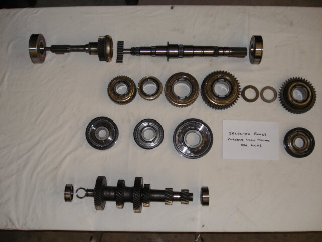
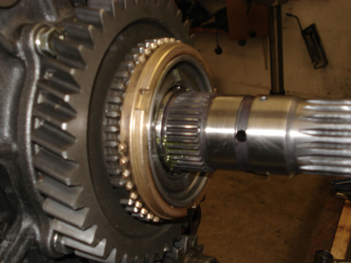
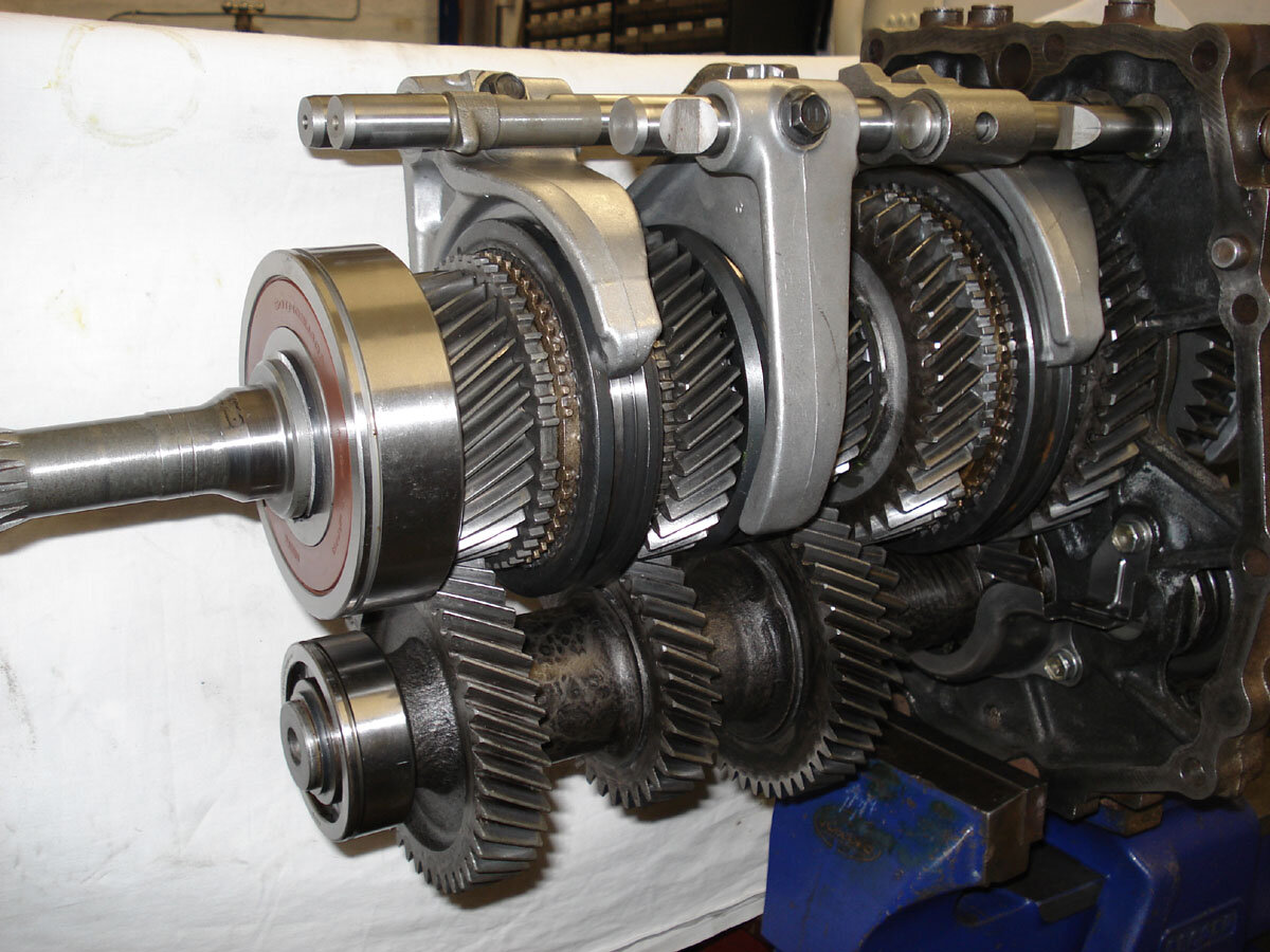
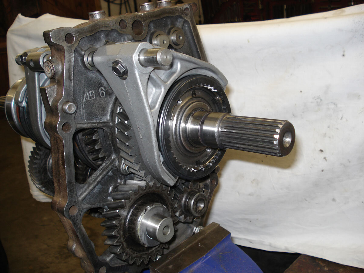
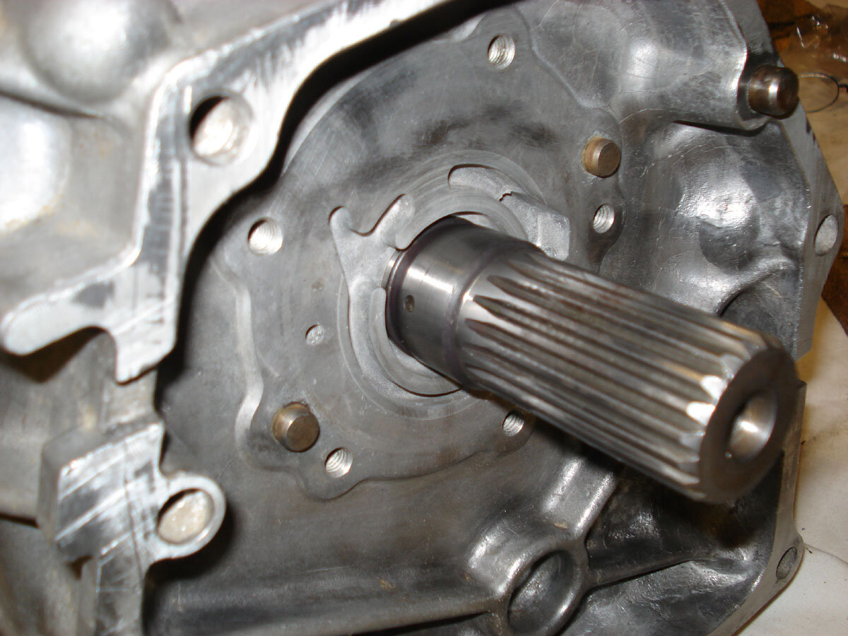
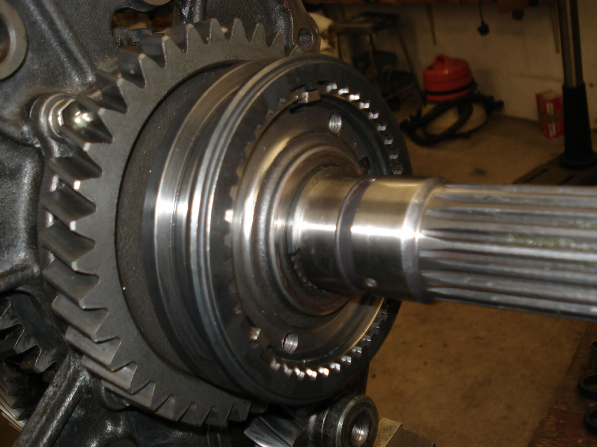
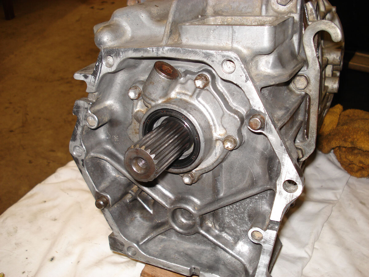
The box in bits showing some of the damaged components:

IMAG0764.jpg


IMAG0765.jpg


IMAG0766.jpg


IMAG0767.jpg


IMAG0769.jpg


IMAG0770.jpg


IMAG0773.jpg


IMAG0775.jpg


the 1st & 2nd gear synchros are also so worn as to be useless, not sure if they are just old or another casualty of the poor rebuild.
 
Last edited:
This is what it should look like when it's built up again (picture is of Frank's box after that was put back together) before the casing goes back on. The front / input is on the left of the picture. Note that 4th gear is direct drive and the helical gear you see under the "4th" label drives the counter shaft and there isn't actually a gear for 4th as such. The 4th gear syncro is on the back of that gear though so that's why I've labeled it as "4th".

LC%20gearbox%20dismantle%20044%20anotated.jpg
re Frank will put me right if I'm getting any of this wrong.
 
Last edited:
I've grabbed and annotated the EPC exploded parts diagram. It makes a handy memory aide during reassembly and is an easy way to check which new part no. goes where. The part numbers are just for the parts that might be replaced in a normal rebuild. Where 2 parts numbers are listed (the synchro ring sets) the first part number is 08 1992 to 08 1996 and the second part number is 08 1996 onward (manufacture dates) they are not interchangeable, they are physically quite different. The part numbers given for the snap rings are for the first size in the series for easy reference to the right pack of snap rings for that location. Click on the picture to see the full size version if it looks a bit small.

merged.jpg
 
Last edited:
Subscribed, thank you for sharing, been waiting for this!
 
Last edited:
To recap; Jon gave me Ian's old box to play with. On considering rebuilding it I first needed a workshop manual to see where the original rebuilders had gone wrong. Apart from the obvious. I found several manuals and took witness statements but there were so many different stories that the only way out of this problem was to take my own identical gearbox apart. This box has done 130,000 miles but the synchros on 2nd and 3rd were weak. All the parts were in as new condition apart from the synchros which were ground in slightly and the box is now back in the car and the synchros are much improved.

This will be a rebuild thread with a road test at the end.

Frank
 
gearbox%20rebuild%20015.JPG
e dirtiest to cleanest part has to be the oil strainer. Have a look at what Frank found in this one!

Peeling back the edges to get the bottom off
gearbox%20rebuild%20001.JPG
esn't look good from this side
gearbox%20rebuild%20004.JPG
oks even worse from this side!
gearbox%20rebuild%20007.JPG
eaned up
gearbox%20rebuild%20009.JPG
ck together
gearbox%20rebuild%20011.JPG
l the parts laid out ready for reassembly
gearbox%20rebuild%20013.JPG
MG]http://www.mudtoys.com/elcoc/gearbox rebuild 015.JPG[/IMG]

Photos courtesy of Frank
 
Last edited:
Don't like the adverts?  Click here to remove them
lc%20thread%20009.JPG
ion, for an 0892 to 0896 box, the 0896 onward may be different, we'll let you know when one of those is in bits :icon-cool:
lc%20thread%20006.JPG
MG]http://www.mudtoys.com/elcoc/lc thread 004.JPG[/IMG]

offset sliders, the rest are symmetrical.
lc%20thread%20004.JPG
otos courtesy of Frank
 

Attachments

  • lc%20thread%20001.JPG
    lc%20thread%20001.JPG
    149.4 KB · Views: 1,308
Last edited:
Interesting stuff Jon. Looking forward to the outcome of this:icon-biggrin:
 
with all new bearings, all but one new synchro and Frank on the job I think the outcome is pretty predictable Karl :icon-cool:
 
Sounds good.

So whos truck is this going into for the big test? Any cost just for the parts needed yet. PM me if you prefer. Just thinking out loud thats all.:icon-wink:
 
Frank's current plan is to swap it into his 80. Every box will be different as to what parts it needs but I got all the bits for a newer box so I can rebuild mine when it eventually wears out and Frank got all the bits for this older box so we know what they cost :icon-wink:
 
We have been tinkering with this again, here is an almost step by step build of the main shaft.

ian's%20gearbox%20rebuild%20010.JPG
shaft ready for action after Frank has reground the gear bearing surfaces to be perfectly flat again as they were a bit worn.

ian's%20gearbox%20rebuild%20012.JPG
ear is a push fit on its bearing and then the synchro ring set and then the 1st/2nd hub is pressed on. When pressing the hub on be sure to keep everything lined up or you could easily damage the expensive synchro rings. Don't forget the snap ring.

ian's%20gearbox%20rebuild%20014.JPG
ear is a push fit on its bearing.

ian's%20gearbox%20rebuild%20017.JPG
ll the peg in its hole and push the 1st gear thrust washer on.

ian's%20gearbox%20rebuild%20021.JPG
the bearing on being careful to make sure the thrust washer doesn't become dislodged from the peg.

ian's%20gearbox%20rebuild%20024.JPG
e work on the other end of the shaft

ian's%20gearbox%20rebuild%20027.JPG
ear is a push fit on its bearing, along with the synchro ring and then press the 5th gear hub on. Again be careful everything is lined up when pressing the hub on and don't forget the snap ring, not shown in this pic.

ian's%20gearbox%20rebuild%20031.JPG
ear is a push fit on its bearing, along with the synchro ring.

ian's%20gearbox%20rebuild%20034.JPG
press 3rd/4th hub on and again, be careful all is lined up correctly. Don't forget the snap ring, not shown in this pic.
 
Last edited:
ian's%20gearbox%20rebuild%20065.JPG
't replacing the bearing this wouldn't have been disturbed.

ian's%20gearbox%20rebuild%20046.JPG
http://www.mudtoys.com/elcoc/ian's gearbox rebuild 048.JPG[/IMG]
also new roller bearings to go inside the input shaft

ian's%20gearbox%20rebuild%20048.JPG
http://www.mudtoys.com/elcoc/ians gearbox rebuid 001.JPG[/IMG]
4th synchro in place on the back of the input shaft then mount it on the end of the main shaft.

ian's%20gearbox%20rebuild%20052.JPG
http://www.mudtoys.com/elcoc/ian's gearbox rebuild 040.JPG[/IMG]
new bearing on the lay shaft. The bearing comes with a spacer specific to that bearing.

ians%20gearbox%20rebuid%20001.JPG
G]http://www.mudtoys.com/elcoc/ian's gearbox rebuild 055.JPG[/IMG]
put the other end of the lay shaft through the hole in the main plate, because of the angle you can't do this with the bearing fitted

ian's%20gearbox%20rebuild%20039.JPG
fit the inner part of the bearing which is in two pieces.

ian's%20gearbox%20rebuild%20040.JPG
the bearing outer on and then wiggle the lay shaft and bearing back through the hole and fit the snap ring.

ian's%20gearbox%20rebuild%20043.JPG
he oil retainer.

ian's%20gearbox%20rebuild%20055.JPG
plate.

ian's%20gearbox%20rebuild%20045.JPG
se thrust washer

ian's%20gearbox%20rebuild%20057.JPG
se gear is a push fit on its bearing, along with the reverse synchro ring. Be careful not to disturb the thrust washer.

ian's%20gearbox%20rebuild%20063.JPG
everse gear hub has to be hammered on with a drift as per the manual. Make sure everything is aligned correctly, it helps to have someone hold the synchro ring and gear in place so as not to damage the synchro ring and make sure the reverse thrust washer doesn't come off its peg.

ian's%20gearbox%20rebuild%20069.JPG
ng there :icon-cool: pics courtesy of Frank.
 

Attachments

  • ians%20gearbox%20rebuid%20004.JPG
    ians%20gearbox%20rebuid%20004.JPG
    246.6 KB · Views: 1,283
  • ian's%20gearbox%20rebuild%20004.JPG
    ian's%20gearbox%20rebuild%20004.JPG
    112.4 KB · Views: 1,192
  • ian's%20gearbox%20rebuild%20070.JPG
    ian's%20gearbox%20rebuild%20070.JPG
    104.6 KB · Views: 1,083
  • ian's%20gearbox%20rebuild%20073.JPG
    ian's%20gearbox%20rebuild%20073.JPG
    154.6 KB · Views: 1,834
  • ian's%20gearbox%20rebuild%20074.JPG
    ian's%20gearbox%20rebuild%20074.JPG
    175.6 KB · Views: 1,311
Last edited:
There's nothing complicated about individual stages with this but there are lots of things to remember to get right, from not destroying synchros when pressing hubs on, making sure thrust washers are seated properly, correct orientation of components, to fitting lots of snap rings. In many cases it will appear to be ok till it is in a truck and self destructs, so make sure you concentrate and double tripple check what you've done :lol: A floor standing press, good selection of press tools and a selection of gear pullers is essential as well.
 
ians%20gearbox%20rebuid%20040.JPG
full]78174[/ATTACH]tor forks, rods and interlocks installed. The FSM shows some of the forks with a different orientation so pictures from the previous rebuild were helpful here. Don't forget the extra ball for 5th/reverse shaft interlock or the snap rings on those shafts not shown in these pics.

ians%20gearbox%20rebuid%20014.JPG
http://www.mudtoys.com/elcoc/ians gearbox rebuid 021.JPG[/IMG]
Time to move back to the bench ready to slide the casings on.

ians%20gearbox%20rebuid%20015.JPG
http://www.mudtoys.com/elcoc/ians gearbox rebuid 033.JPG[/IMG]
ians%20gearbox%20rebuid%20018.JPG
/main casing fitted and snap rings in place at the front then the bearing cover / retainer. Thread sealant is needed on the cover bolts as they are through holes into the main casing.

Fit the top gear selector into the front housing before installing the rear housing / transfer adapter, you can see it the pictures, at this point you can push the rod through the main plate and through the selector.

ians%20gearbox%20rebuid%20020.JPG
housing / transfer adapter in place. Use the 4 longer bolts on the lifting brackets.

ians%20gearbox%20rebuid%20021.JPG
is the oil pump - there are two small pegs that go in the output shaft to drive the oil pump, shown here is one of the holes for a peg.

ians%20gearbox%20rebuid%20025.JPG
ump installed. The pump bolt holes go through so use thread sealant on the bolts to avoid leaks.

ians%20gearbox%20rebuid%20033.JPG
http://www.mudtoys.com/elcoc/ians gearbox rebuid 040.JPG[/IMG]
don't forget the plug in the bottom of the rear housing if you removed it for cleaning.

Nearly done :icon-cool:
 

Attachments

  • ians%20gearbox%20rebuid%20007.JPG
    ians%20gearbox%20rebuid%20007.JPG
    209.1 KB · Views: 1,100
  • ians%20gearbox%20rebuid%20006.JPG
    ians%20gearbox%20rebuid%20006.JPG
    129.9 KB · Views: 1,103
  • ians%20gearbox%20rebuid%20010.JPG
    ians%20gearbox%20rebuid%20010.JPG
    226.5 KB · Views: 1,508
  • ians%20gearbox%20rebuid%20011.JPG
    ians%20gearbox%20rebuid%20011.JPG
    203.2 KB · Views: 1,160
  • ians%20gearbox%20rebuid%20035.JPG
    ians%20gearbox%20rebuid%20035.JPG
    217.3 KB · Views: 1,221
  • ians%20gearbox%20rebuid%20029.JPG
    ians%20gearbox%20rebuid%20029.JPG
    225.4 KB · Views: 1,403
  • ians%20gearbox%20rebuid%20031.JPG
    ians%20gearbox%20rebuid%20031.JPG
    202.7 KB · Views: 1,082
  • ians%20gearbox%20rebuid%20036.JPG
    ians%20gearbox%20rebuid%20036.JPG
    240.1 KB · Views: 1,100
  • ians%20gearbox%20rebuid%20038.JPG
    ians%20gearbox%20rebuid%20038.JPG
    159.7 KB · Views: 1,108
Last edited:
I'm really loving this thread :thumbup:.

Excellent job and write-up, well done :clap:.

I hope it will be a 'sticky'.


Bob.
 
Back
Top