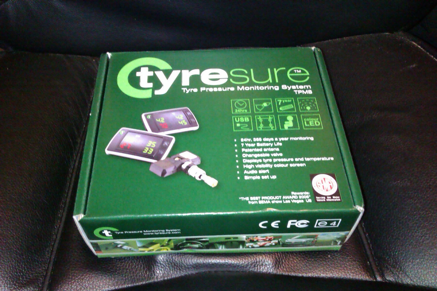
Following on from Grahams thread I decided to get a Tyresure TPMS to play with. I ordered a complete unit from here and an extra sensor and valve from here . The spare sensor is for my spare wheel, seems silly to have TPMS but if you have to use the spare for any length of time not have it monitored.
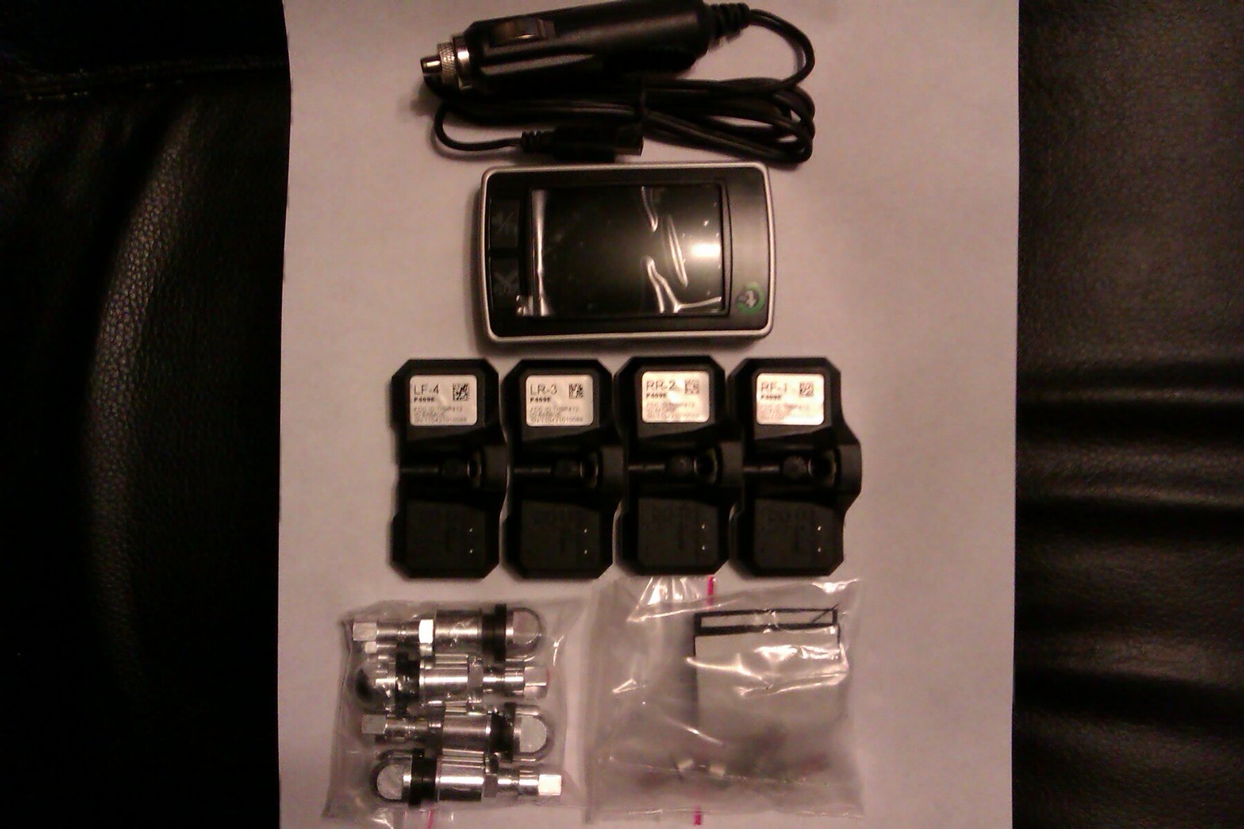
So this is what came:
[attachment=4:1brse25k]IMAG0800.jpg[/attachment:1brse25k]
[attachment=0:1brse25k]IMAG0813.jpg[/attachment:1brse25k]
Even though they give measurements on the web site the main unit is much smaller than I expected, which is a good thing:
[attachment=3:1brse25k]IMAG0804.jpg[/attachment:1brse25k]
The mini usb power connection seems quite big and bulky and may limit where you can position the display unit:
[attachment=2:1brse25k]IMAG0817.jpg[/attachment:1brse25k]
Not ideal so I took it apart to see what the options might be:
[attachment=1:1brse25k]IMAG0822.jpg[/attachment:1brse25k]
The ACC and GND pads are connected to the power input socket so I'll use those to attach a power cable and have it exit through the back of the unit, once I've worked out where am putting it and can choose the exit hole position to suit. There are some other interesting looking connections on the board but for now sorting out a tidy power connection will do.
That's all for now, till I get the sensors fitted in the next week or so and then I'll post again on how well it works and start experimenting with intercepting the sensor data for the Arduino gadget to play with.

 ). Should be ok though, the sensors look much like the OEM ones I could have retro fitted but this is all a bit of an experiment to see if it's very useful after all and a retro fit would cost more than I'm willing to spend on an experiment!