Don't like the adverts?  Click here to remove them

An Ultra slow Ultra4 build

Hey Guys,

Been a while and haven't made much progress on the truck with the holidays and all that, I did say this was going to be a slow build!

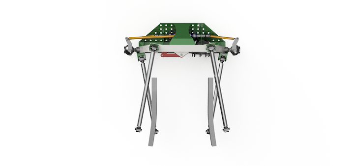
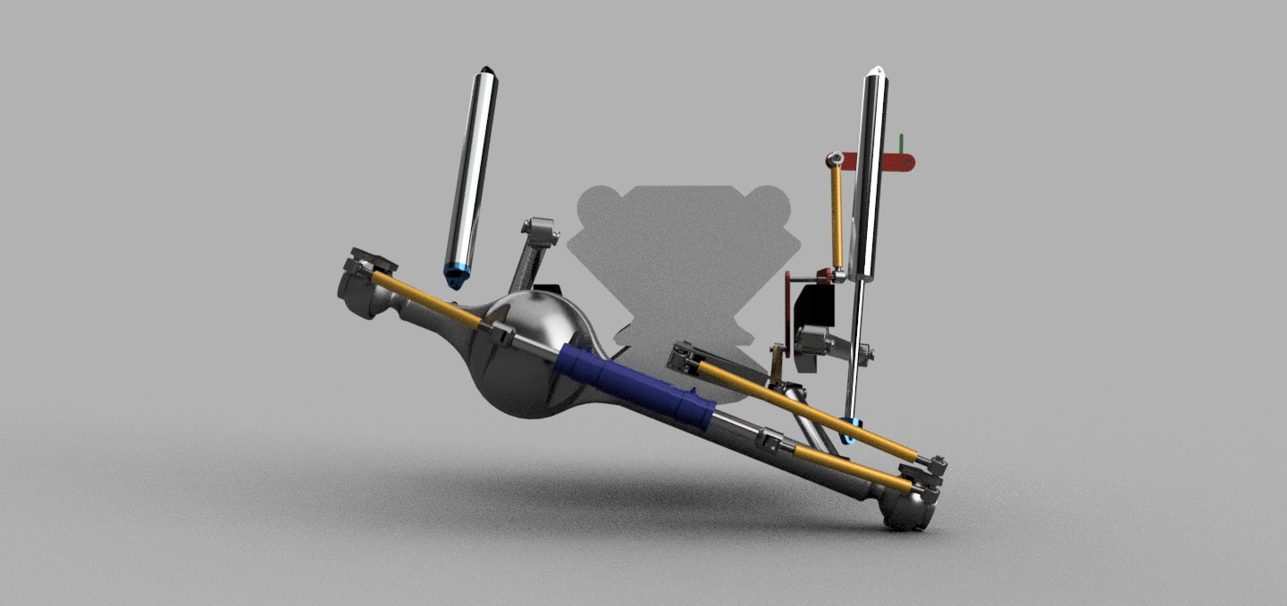
Anyway back to what I have actually managed to achieve. I went ahead and played around in cad to work out what the bumpsteer would be like with the bell crank setup. These are a few shots of the front axle flexed out, I put in links to where the steering wheel will be approx. I get around 15" of bump steer input, but this will be damped sound in the steering so I am thinking in reality it will be negligible. The green indicator shows the bumpsteer generated by cycling through the range of the suspension travel.
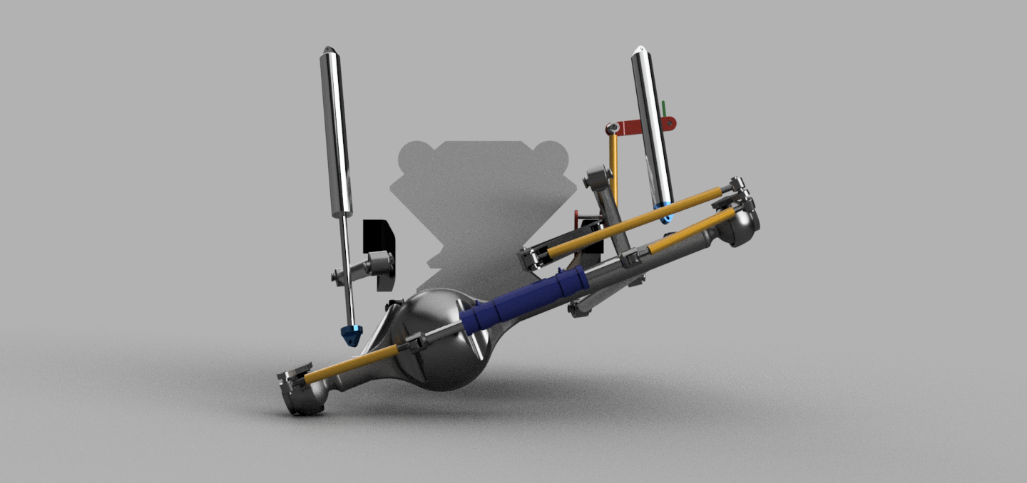
Bumpsteer%201.png
Bumpsteer%202.png

So I am going to continue pursuing this steering setup. Worst case if I can't get it to work I'll race in Legends class with full Hydro until the next season.

So that has led me to start playing around with links. I mate of mine had to abandon his build due to a change in circumstances. He bought a roller and parted it out. So i had the opportunity to pick up a set of 2.5" 7075 Aluminium links with 2.5" Johnny Joints. His wheelbase was going to be 116" so I figured why not try give it a shot with his link lengths and see what I can come up with. worst case I may need to trim his links down or cut longer ones.

So this just a little test fitting to see roughly where things can fit after which I took measurements and plugged them into the Triaged 4-link calculator.
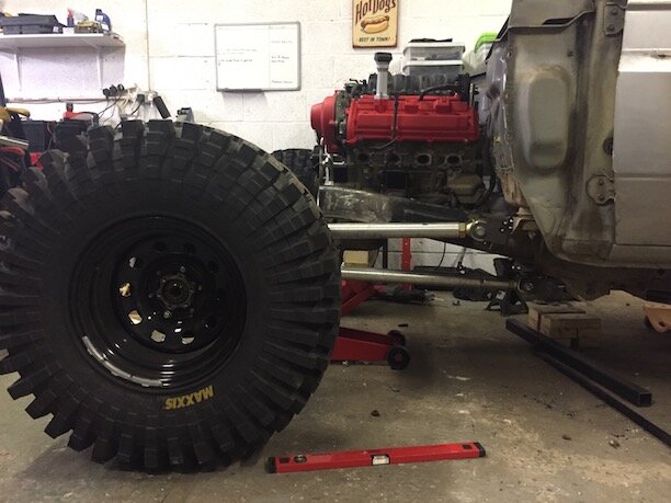
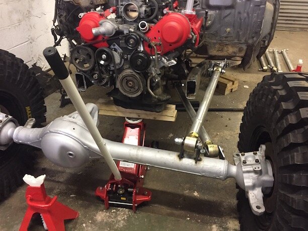
4-link1.JPG
4-link2.JPG
4-link3.JPG
4-link4.JPG
4-link5.JPG

As the links are fitted in the pics above the numbers turned to not be great. The diff pinion angle change was in excess of 20' and put the pinion pointing into the motor at full compression. But it was a starting point. So I played around in the Triaged calculator and in CAD to figure out what was feasible and have come out with the following numbers, Ignore the rear I haven't started on that yet.
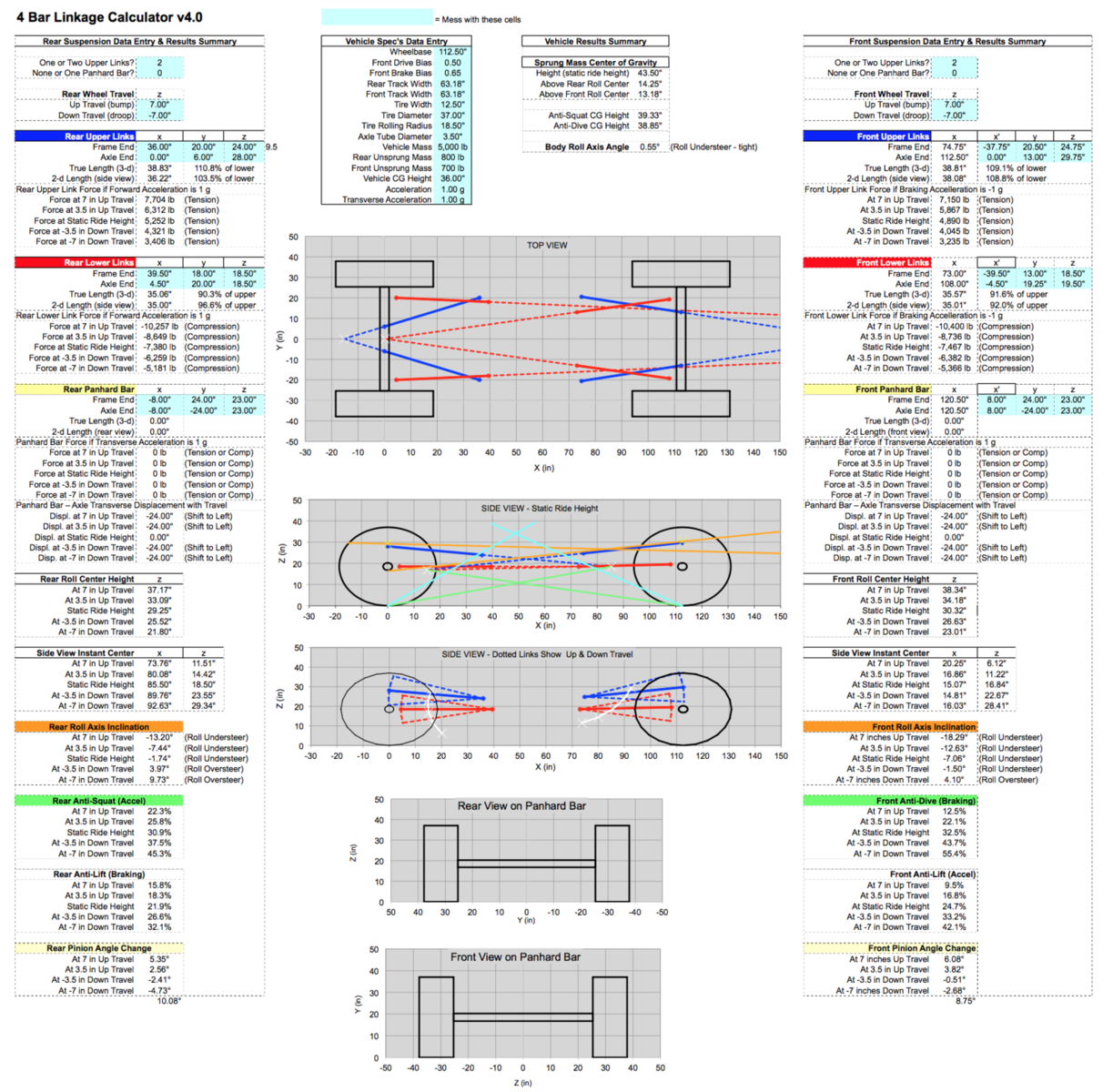
4-Link%20Numbers.png

So from that I have gone on to start the design for the truss, Ram mount, Bellcrank and link mounts. I still need to do the chassis mounts. This is where I am at.
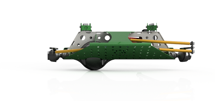
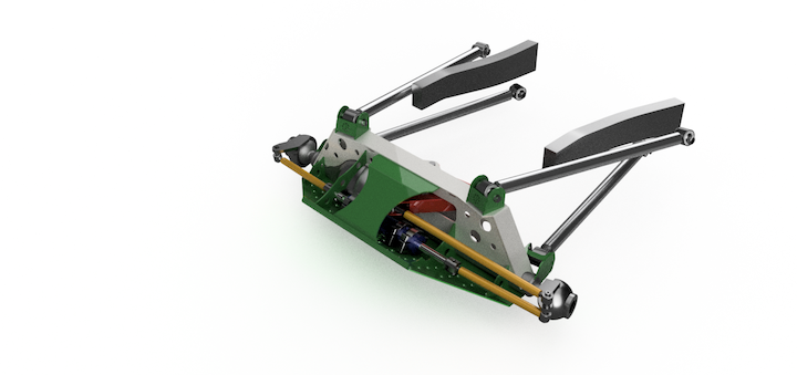
Render%201.png
Render%202.png
Render%203.png

I need to still do the shock mounts and bump stop pads and then tidy up a few of the tabs. I like using a slot and tab setup, it saves me having to rely on a tape measure too much and helps keep things symmetric.

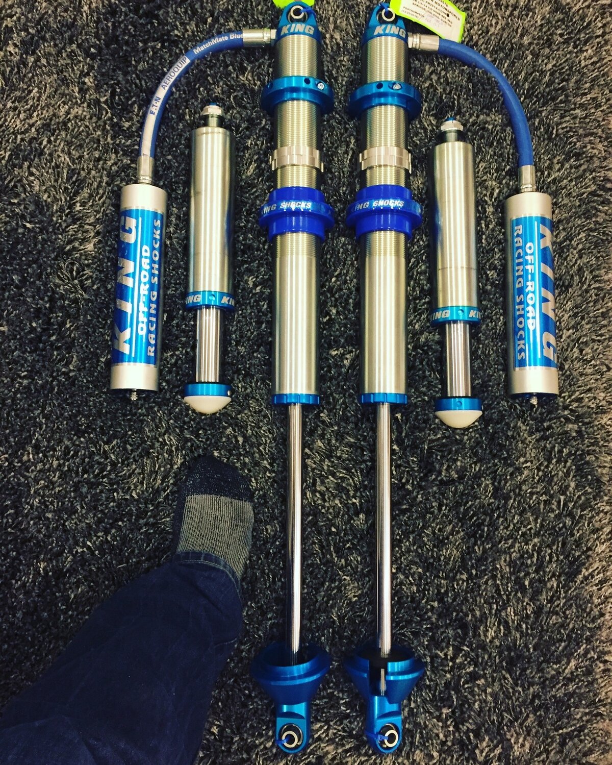
Other than that the shocks are ordered and should be with me at the end of the month. I went for the King 2.5"x14" RR coil overs. So looking forward to getting those in. By then I should have all the laser cutting done for the front truss and chassis mounts.
 
This thread brings me joy and jealousy. In that order. This build is going to be pretty awesome and oh how I wish I had a garage to work in! I'd strip so many bits off to clean and love that I wouldn't be able to put her back together again :)
 
Thanks Guys, I finally finished up the front axle design for the truss and chassis mounts. The parts are cut so I'm gearing up for a productive weekend ahead of me.
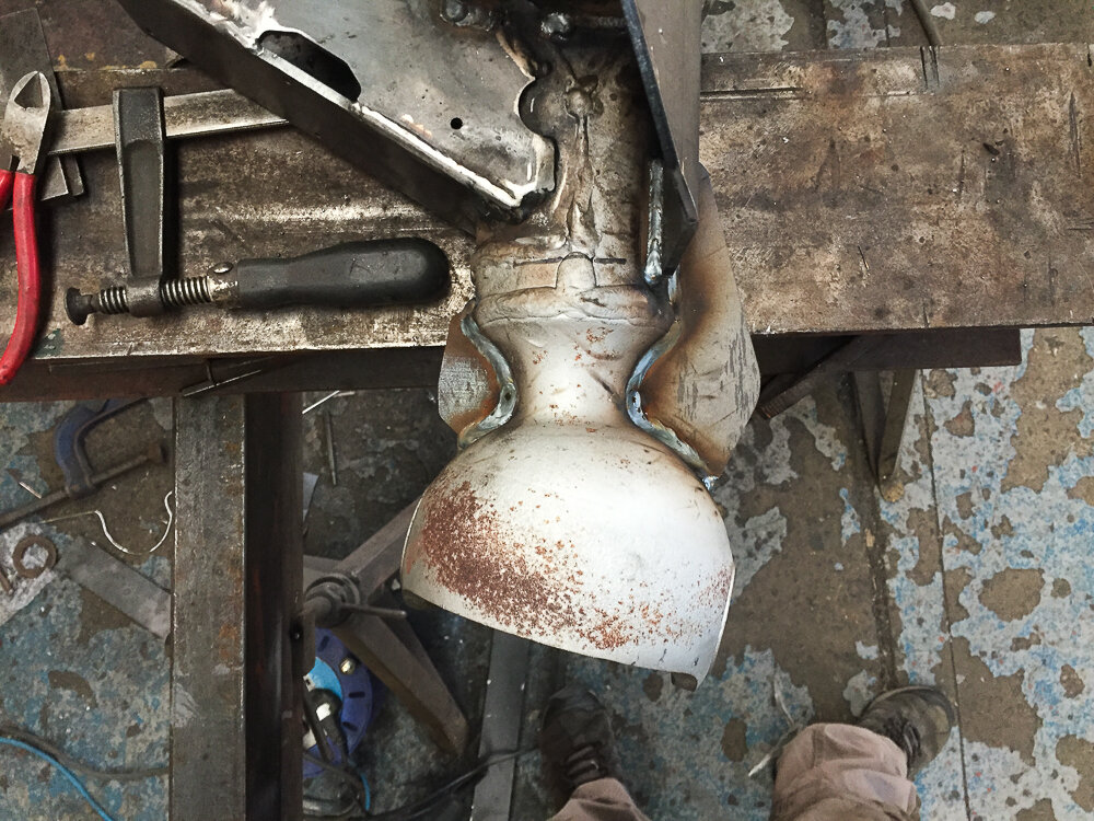
In the meantime I did get an early birthday present...

King%20Shocks.JPG

These are beef! Thats my size 9.5 trotter next to them...
 
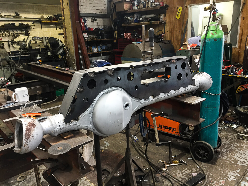
Ok, so thanks to a mate of mine it was a really productive day in the workshop yesterday.

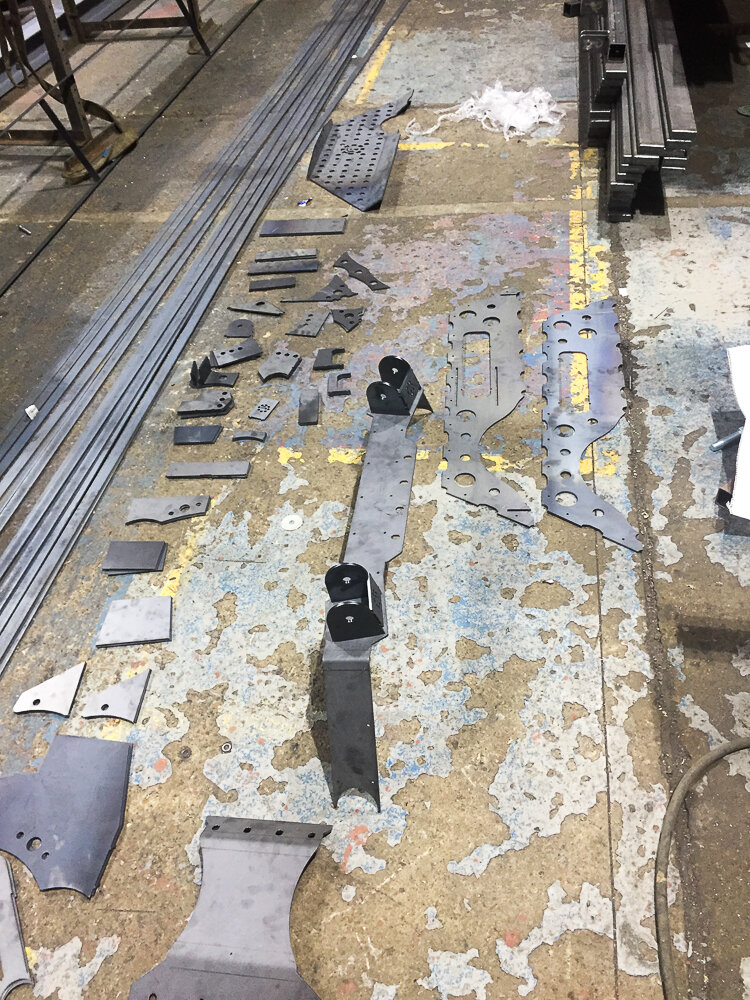
These are the puzzle pieces for the front axle and chassis mounts.

IMG_4261.jpg

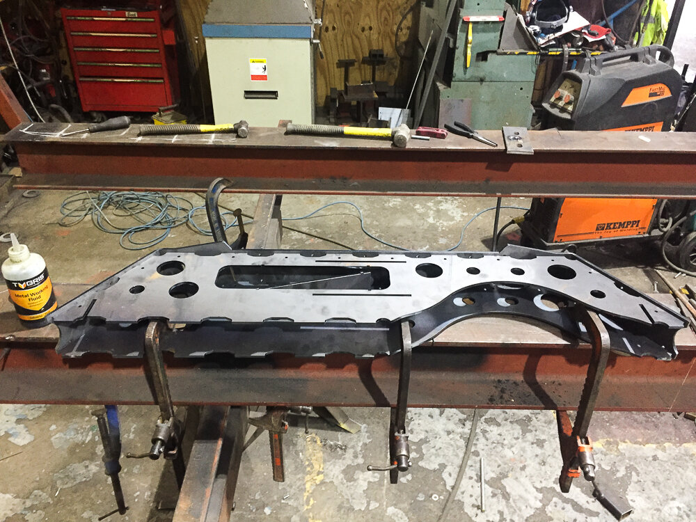
We tacked up the truss assembly on the bench
IMG_4266.jpg

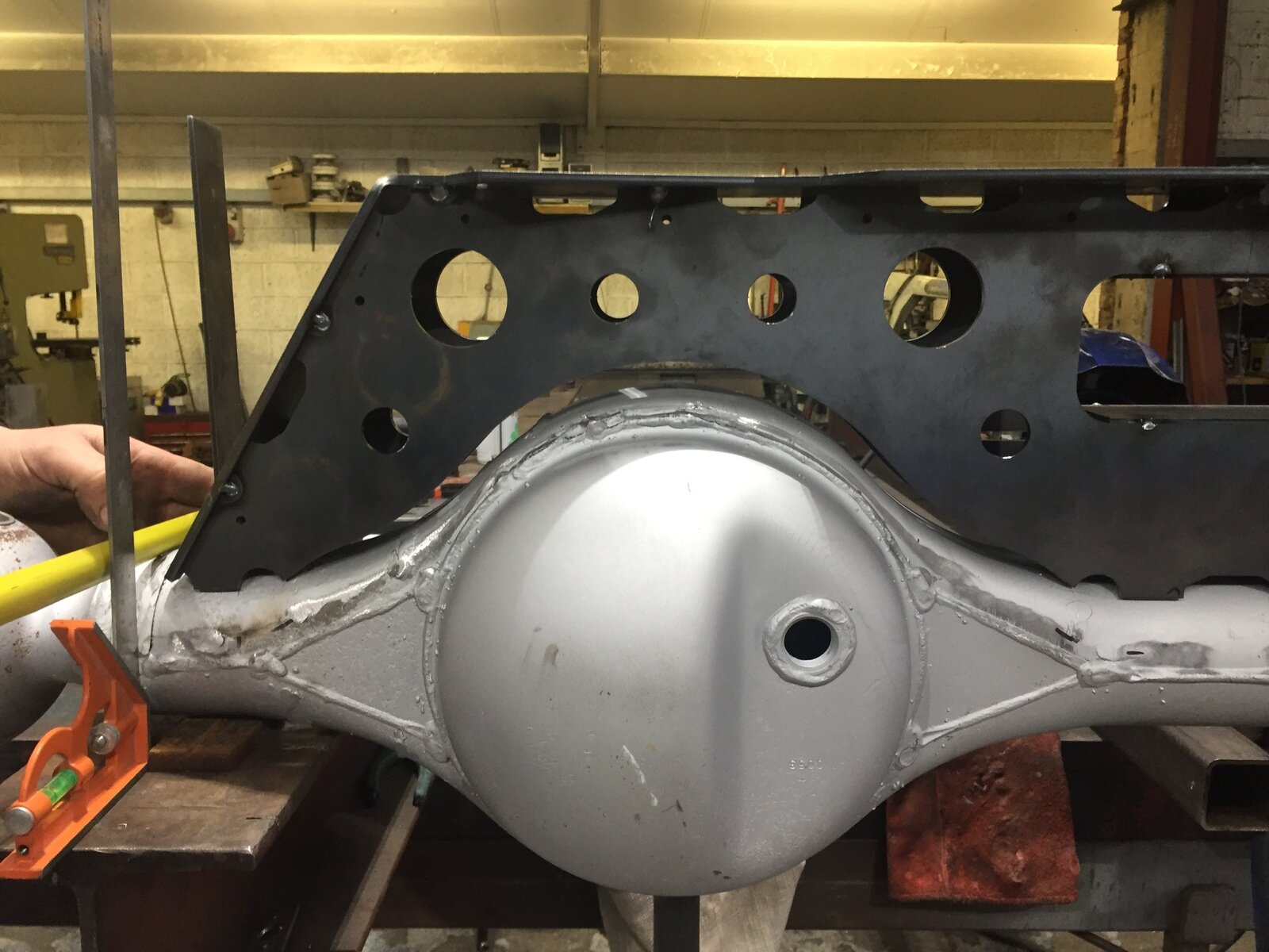
Afterwhich I found I had made a mistake with the axle tube outside diameter which made the entire assembly sit too high on the axle due to the front and rear profiles not being far apart enough. The bottom of the from profile should sit just above the weld at the centre of the axle.
IMG_4268.JPG

I'm a bit confused as to how I managed to cock that up but hey ho we moved on and made a plan...
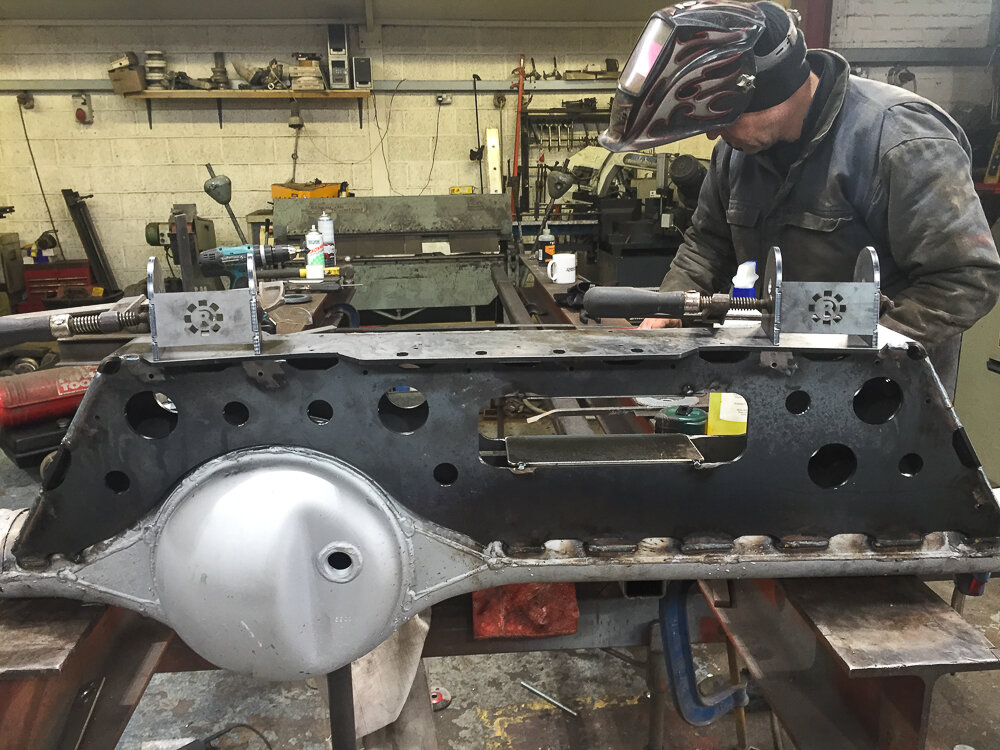
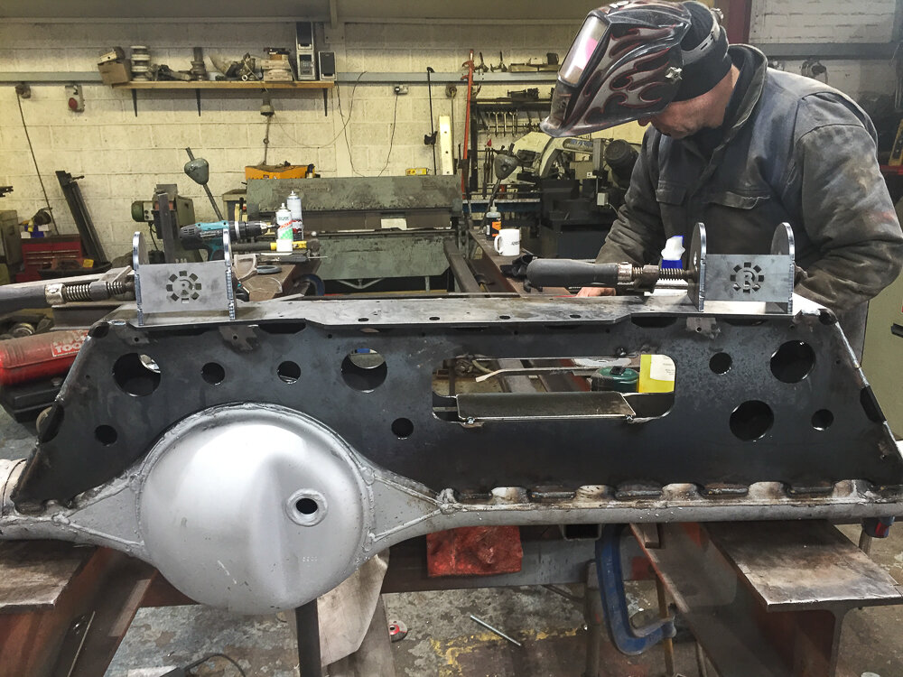
IMG_4269.jpg

IMG_4270.jpg

IMG_4274.jpg
Top links going in.

IMG_4274.jpg

IMG_4278.jpg

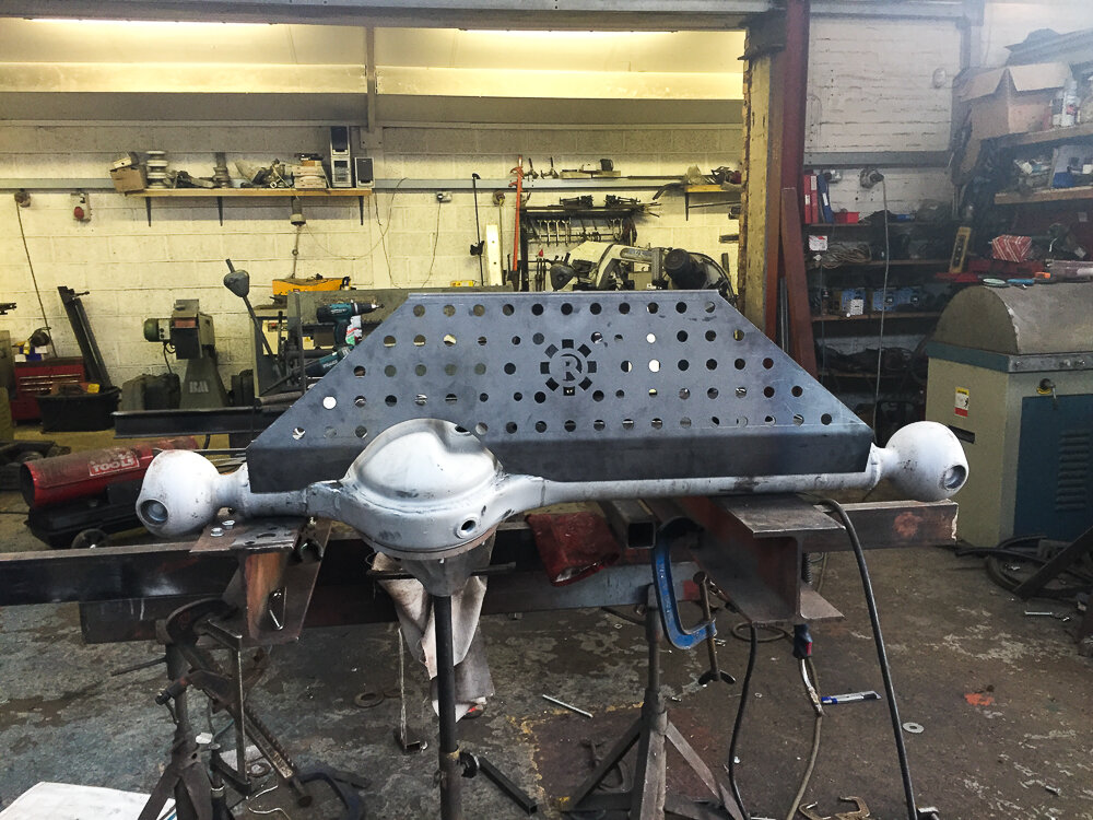
Skid plate and Ram mount going on

IMG_4281.jpg

1omm gussets going onto the knuckles, apparently a bit of a weak spot on these axles when you start abusing them.

IMG_4296.jpg

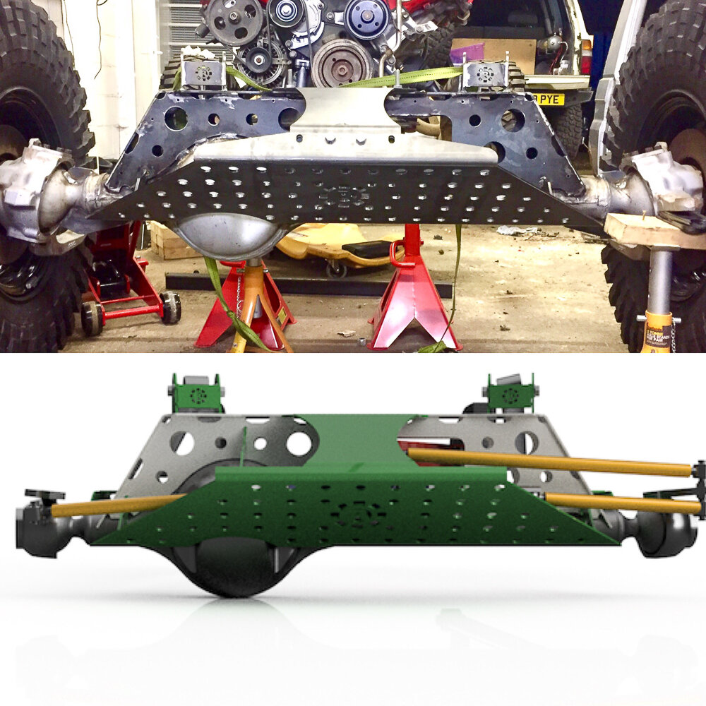
And a little comparison of the Cad and end product. Next I need to fabricate the chassis mounts and then finally the lower link mounts on the axle. After that I'll need to cycle the suspension to check clearances and see if I need to tweak anything. Looking at it as it stands I think I'll need to raise the ride height a couple of inches, given I was shooting for a fairly low height the impact shouldn't be too detrimental.
 
Nice work mate! :clap:

This truck is going to be one hell of a thing when its finished, hats off to you mate, I wouldnt know where to start! :thumbup:
 
Don't like the adverts?  Click here to remove them
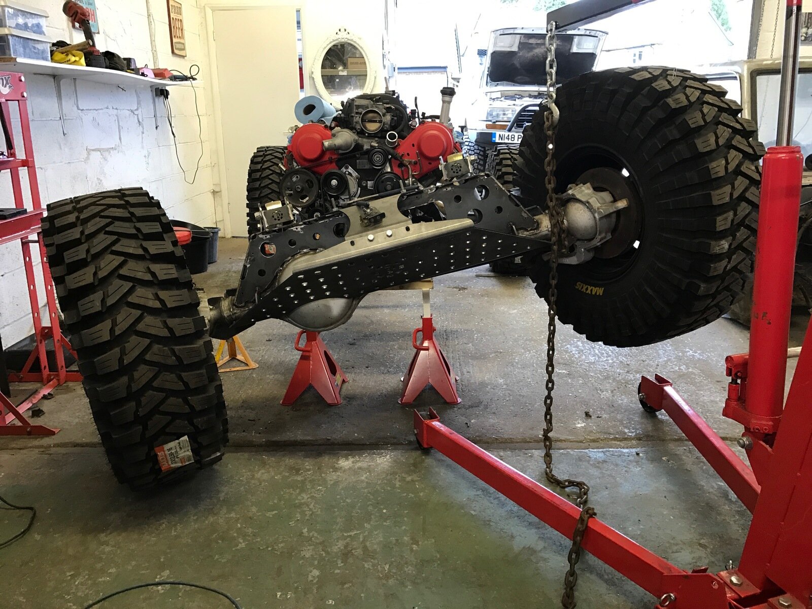
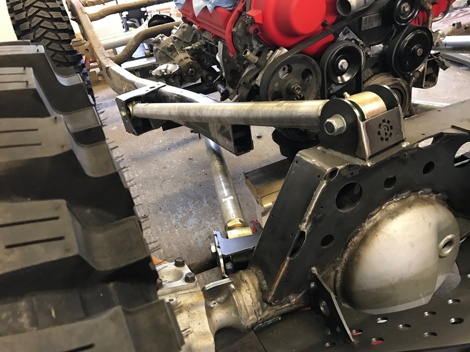
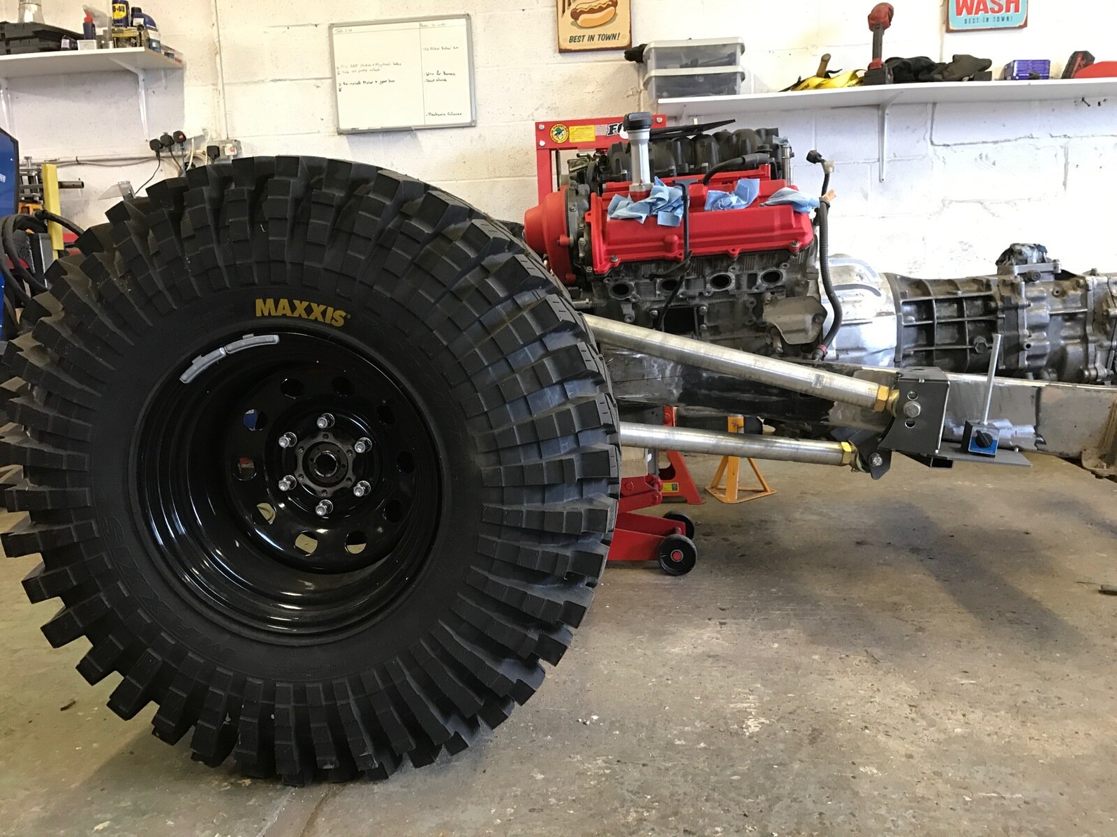
A bit more progress this weekend. I have the Upper link mounts on the chassis tacked up and ready to be welded. The lower links are in place but the actual mounts aren't finalised. But it did get me to a point where I can cycle the the front axle to check for any clearance issues.

IMG_8363.JPG

IMG_8046.JPG

IMG_8917.JPG

And this is full bump...

IMG_9355.JPG

IMG_6858.JPG

The upper passenger side Upper link gets pretty close to the power steering pump. I will more than likely move the pump and am definitely moving the alternator. So that issue should be resolved in due course.

I think I have plan for incorporating the lower link mounts into a tubular sub frame of sorts that will tie into the roll cage, so next step is to start with the bulkhead and cage mounts, that way I can see how I can tie it all together.
 
Wow.

Looks like it's going to be a beast.

You have certainly moved it to a new level. can't wait to see this in action.

The front axle is a work of art.

Stu
 
So I figured an update was overdue.

I have been away for a few weeks so not as much has been done as I'd like but I am now able to put in a few days during the week so progress should speed up somewhat.

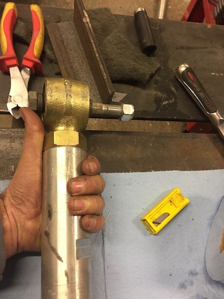
The lower link mounts are tacked in place, I think this is a stronger and more stout solution that I had previously drawn up. I will be adding in further bracing once I have a crossmember in place for the rear link mounts.
Lower%20link%20mounts%201.jpg


Lower%20link%20Mounts%202.JPG


The box for the upper mounts will be coming out too and replaced with a section of tube that will brace the sill/ slider bar to the chassis rails. It seems like it will be a neater solution and will improve clearance. Looking at the boxed mount now and how low it is relative to everything else I think it'll keep getting caught up on stuff.

Then I started with the roll cage. I am using software called bend tech. I have to say it's awesome, there is no way I could have bent and notched the tube I did as well as I managed to without it. Whats really clever about it is that it calculates your notches for you, you then print out a template of the notch that you stick onto the tube and then mark where you need to cut. On the template you have match marks and distance marks to make sure that when you need to notch both ends the notches are in the correct orientation to each other and far apart enough.

This is the type of notch you end up with:

Notch%201.JPG


Notch%202.JPG


So this is the idea, I haven't finished the front yet.

Side%20View.jpe

Top%20View.jpe

Iso%20View.jpe


This is it taking shape

Rollcage%201.jpg


Rollcage%202.jpg


The box section frame for the seat is only temporary. This was just used to fine my ideal seat position and height.

Im back at it tomorrow, planning on getting the B-Pillar area and rear section of the cage done. The two sill/slider bars were the hardest to bend up, I'd be lying if I said it didn't take a few attempts.
 
Last edited:
I reckon we are honored by your taking the time to share all this with us Ryan :thumbup:
 
Great work! :thumbup:

Are you planning on using any of the 70 cab still, or is it now going to be all tube work? :think:
 
I reckon we are honored by your taking the time to share all this with us Ryan :thumbup:

:text-+1: It's fantastic to see this coming on, Ryan.

Do you have spec regs to work to? It would be a disaster if there are tech regs in competition that ruled you out at scruitineering time.

I'm sure you've taken these on board, just thinking aloud...
 
Great work! :thumbup:

Are you planning on using any of the 70 cab still, or is it now going to be all tube work? :think:

Thanks dude. No I have decided to ditch the cab altogether I can getaway with just using the fenders, Bennett and front Grill and still be class compliant. So it'll be mostly tube work with the original chassis rails from the engine mounts to just behind the seats.
 
  • Like
Reactions: Ben
:text-+1: It's fantastic to see this coming on, Ryan.

Do you have spec regs to work to? It would be a disaster if there are tech regs in competition that ruled you out at scruitineering time.

I'm sure you've taken these on board, just thinking aloud...

Thanks Clive. I'm keeping on top of the regs and have been looking at slot of the other vehicles, both UK and US which is giving me a good steer on what I can and cannot do.
 
Hey Guys,

Been a while since my last update. A fair bits happened since then.

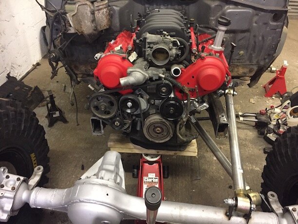
So while I waited for the laser cutting to be completed for the rear axle I spent some time figuring the front end out. I ended up cutting the tubes either side of the motor back. They weren't going to work the way they were. A bit of a lesson learnt here regarding the cage, don't make the tubes too complicated by adding multiple bends in multiple planes. The next one I build I'll try keep it to a max of two bends in a tube.

Anyway, back to the front end. I trimmed the fender somewhat and built the framework for the fenders to mounts to.

FullSizeRender%202.jpg


FullSizeRender%204.jpg


IMG_4497.JPG


IMG_0910.JPG


I managed to figure out what I was going to do for the frame within the cab, this was however the 4th iteration...

FullSizeRender%206.jpg


IMG_9052.JPG


FullSizeRender%205.jpg


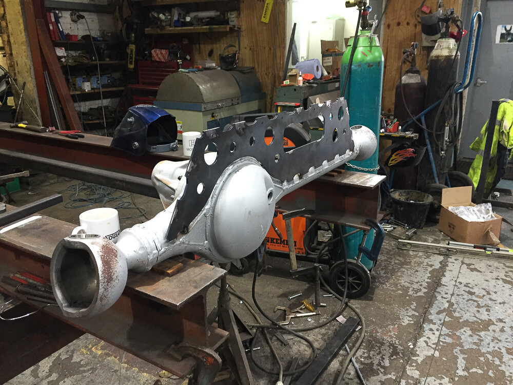
The rear axle profiles came in so that was the next job to be tackled. This is the CAD model I did.
ARear%20Axle%20Housing%20v40.jpg


ARear%20Axle%20Housing%20v40.png


ARear%20Axle%20Housing%20v41.png


And this is how it turned out...

IMG_8017.JPG


IMG_1293.JPG


IMG_2235.JPG


IMG_7819.JPG


IMG_9960.JPG


Then I went on to do the shock mounts. I have the rear figured out but I still need to figure out the front shock mounts, what you see in the pics is temporary and was purely to allow the truck to support its own weight so that I could get it onto a trailer for the workshop move.

IMG_1854.JPG


IMG_3389.JPG


Then came the workshop move, what a ball ache that was...

IMG_7823.JPG


IMG_0302.JPG


So that is it for now. The new workshop is a mess so there wont be much progress over the next week or so. I have relegated myself to the fact that it wont be ready for the King of Wales race in July, so targets are now set on the King of Britain race in October, which is fine. I'd rather not try rush it and I should also then have a good bit of time for testing and working out niggles.
 
Back
Top