Don't like the adverts? Click here to remove them
You are using an out of date browser. It may not display this or other websites correctly.
You should upgrade or use an alternative browser.
You should upgrade or use an alternative browser.
A different approach to 80 series front axle rebuilds. Really?
- Thread starter Chris
- Start date

- Joined
- Mar 1, 2010
- Messages
- 5,688
Hi 898kor
If you set to the factory preload then undo the 4 nuts until there is just no play in the bearings there is about a .75 mm air gap on top of the shims so this is disappearing somewhere. The ball is uncrushable but the outer housing stretches by this amount. If you measure the top and bottom seal retainer bolt holes you can measure the stretch. As I say I was so horrified I only used 1/2 preload. My old races had no play in them but when I got them out they were like corrugated iron. The car had mostly done commuting explaining why all the wear was in the straight ahead position. Even with the rollers seated in these grooves there was still preload left. Metal either expands or contracts in any preload situation you can't get rid of an air gap otherwise. Like in a diff pinion preload the pinion shaft stretches.
Fraank
As I said, Frank I am with you on the theory and in your observations, but I'd add this question. Does it matter? The casing is cast and I would hazard a guess that it is SG (Speroidal Graphite) rather than grey iron. SG is sort of a steel substitute. It casts well and is relatively cheap. It's immensely strong and has many good properties. I worked in a foundry for many years where our principle products were diff carriers and swivel hubs (OK OK yes for Landrovers) and these were SG. As we know, diff carriers flex under load which is why they skip teeth sometimes under heavy load. We didn't design the rubbish they use in LRs we just cast them.
What I am suggesting is that IF this crushing is actually supposed to happen if you follow me, than is it a problem? To be clear though, I am asking if it IS a problem, I an NOT saying that it ISN'T a problem. But SG iron would certainly cope with this sort of flex.
Would I be right in saying that if it had top and bottom shim adjustment, we probably then wouldn't see this?
Citizen Brown
Member
- Joined
- Oct 18, 2013
- Messages
- 110
- Country Flag

Great thread Chris and nice clear pictures. Keep up the good work but please keep it simple (ie assume no engineering knowledge and certainly no miller in garage!) also that (like mine) viewers tool kits might consist of a fine selection of hammers and a screw driver I made in a metalwork lesson in 1978!
- Joined
- Mar 1, 2010
- Messages
- 5,688
Agree with all you say Chris. I just bottled out of using the whole preload. I've never heard of a hub splitting open. Be interesting to see what you think if you have a look at the gap closing up. The hub is pinched bottom to top by the bearings so I don't think where the shims are would matter.
I've also found that oil seals can leak if fitted into a groove even if they are a tight fit. The seal wanders up to a higher level on the shaft when the shaft is spinning as on a flat belt running up a barrel pulley. This behaviour is unpredictable. The purpose of the speedisleeve is to provide a parallel surface rather than to increase the diameter of the groove. I normally polish light grooves in the lathe and risk it.
Frank
Don't like the adverts? Click here to remove them
Frank have you tried machining that area of the shaft at all? I wondered if it was ground and hardened somehow. I had thought about facing it up. The gooves on these are not that deep. I have seen worse. I get the rolling barrel concept. Again though, it was not in that good repair in there but not leaking one drop. There was plenty of oil in the retainer behind the seal when I pulled it. I have no idea of the cost of Speedisleeves. I have measured the shafts at 35.02 and there is a sleeve to fit that. Might give them a ring. I could add that to the build thread.
Right, in the interests of research, 2 Speedi Sleeves CR99139 ordered. Total cost £40 so they aren't cheap. The wear on one shaft is 0.135 mm and on the other, 0.065 across an area of only around 4 mm along the shaft. Personally I think this is nothing. In fact with a straight edge across the high points, you can only just see light coming through. But they feel worse than that to the touch. I would stick these back in no problem but this is a quality build and we shouldn't cut corners.
Fitting them might prove interesting. It's been done I know but I have never seen a write up. Effectively I would rather fit them on from the diff end, but they'll have to go on from the CV end. The wear patterns are different on each shaft so the seating of the sleeves will be different too and they are only 15mm deep. So that will need to be quite accurate so as the repaired area of the shaft floats in and out, it doesn't slip out of the seal causing possible damage.
Off to You Toob for a search
Olazz
Well-Known Member
- Joined
- Apr 23, 2010
- Messages
- 1,428
- Country Flag

Right, this is a quality build and we shouldn't cut corners.
SKF SPEEDI-SLEEVE Gold has been thoroughly tested to establish its level of abrasion resistance in severely contaminated environments using both coarse and fine sand.
Under these conditions, seals on shafts without an SKF SPEEDI-SLEEVE Gold protection started to leak after 450 hours on average. Seals on SKF SPEEDI-SLEEVE Gold ran for an average of 2,500 hours.
I trust you went for the Speedi Sleeve GOLD and not the cheapo std version CJ...

- Joined
- Mar 1, 2010
- Messages
- 5,688
I don't know if the shafts are hardened. I can't remember how bad or not mine were but not that bad or I would remember having have done something about it. I might have spun them in the lathe with some 1000 grade paper and the 2000 grade paper and brasso, just can't remember exactly. The speedisleeves I used years ago were stainless steel and came with a fitting kit. You'll have to copy that a lot longer to get the sleeve onto the shaft then turn the shoulder off. That's if they are the same as mine were. I think they had just been invented when I first used them, no not just after the wheel. I bought them just over the road from my office in Bearwood Bham. I walked to their store over the cobbles and dodging the carriages. All very interesting.
Frank
Frank
- Joined
- Mar 1, 2010
- Messages
- 5,688
PS
If you feel like using Loctite you can apply it after fitting. It is just as effective this way and ensures you can get the sleeve in exactly the right position with getting it stuck in the wrong position. Loctite will creep into the smallest of cracks. I have a very old bronze bodied regulator for my air supply. It was porous and hissing slightly so I turned off the pressure and dribbled Loctite over the area and left it overnight. Cured it.
Frank
These are stainless too Frank. They are just about at the top end limit size range wise so they wont need locktite, they will be snuggly. The sleeves come pre-cut / marked if you like and once on position you pull the flange off with pliers. What I don't want is a sharp edge there because it's that edge that will push through the new seal. But like a total knob, I hadn't thought about putting them in the lathe to sort that out if it was sharp. They're extremely thin so I am sure we'll be fine. They'll be here tomorrow but I am in Birmingham.
Well the breakfast weatherman said, ‘If you are planning to work on your drive today, I’d crack on ‘cos it looks shite for later’ So by 09.15 the front diff was out.

I have to say it really is in excellent fettle. In terms of pre load and back lash it feels like a new one. Zero evidence of wear or anything. Shame I don’t have a use for a manual diff.

Here’s the one from stock. Done very few miles and comes from the JW diff clinic. Again, very smooth, backlash and preload all silky smooth. So this is a 4.1 which should bring everything back to square with the 35’s on. Not, I have to say that I have noticed any issues at all on the original ratios except the speedo reading incorrectly by some margin.

The rebuild here isn't just the diff and axles, it's really the front end. Not inc the brakes on this run, but it does include the steering rods.
I hadn't noticed any real wear in the track end joints, but they are as we know, notoriously hard to shift sometimes and when I took the Silver Phoenix to be tracked last time they actually popped a joint by swinging on it. We had heated it and sprayed it but just could not move the threads at all. So, the was really a good time for some PM.

Just as well really as they took some real shifting on the bench..totally solid.
The threads needed a bit of a clean out so I used the old home made thread chaser trick by cutting a nick out of the old one and screwed that in several times to clear out the deepest thread section.

These are Milner ones, yes. I have used them before and never had a problem with them. They seem well made.

New ends in - I have done all 4 on the track and relay rod, but they all look the same. No, they aren't the same, I said they all just look the same for the purposes of the thread.

Took the opportunity to put some new nuts and bolts in there too. The rod turns by hand it's so slick after the clean. The little chap at the tyre shed where I go will think it's his birthday when he comes to track this one. I measured the positions of the old ones before I took them out so they will be pretty much right when I rebuild the steering. Close enough to drive round the corner for sure.
And that's that.
I have to say it really is in excellent fettle. In terms of pre load and back lash it feels like a new one. Zero evidence of wear or anything. Shame I don’t have a use for a manual diff.
Here’s the one from stock. Done very few miles and comes from the JW diff clinic. Again, very smooth, backlash and preload all silky smooth. So this is a 4.1 which should bring everything back to square with the 35’s on. Not, I have to say that I have noticed any issues at all on the original ratios except the speedo reading incorrectly by some margin.
The rebuild here isn't just the diff and axles, it's really the front end. Not inc the brakes on this run, but it does include the steering rods.
I hadn't noticed any real wear in the track end joints, but they are as we know, notoriously hard to shift sometimes and when I took the Silver Phoenix to be tracked last time they actually popped a joint by swinging on it. We had heated it and sprayed it but just could not move the threads at all. So, the was really a good time for some PM.
Just as well really as they took some real shifting on the bench..totally solid.
The threads needed a bit of a clean out so I used the old home made thread chaser trick by cutting a nick out of the old one and screwed that in several times to clear out the deepest thread section.
These are Milner ones, yes. I have used them before and never had a problem with them. They seem well made.
New ends in - I have done all 4 on the track and relay rod, but they all look the same. No, they aren't the same, I said they all just look the same
Took the opportunity to put some new nuts and bolts in there too. The rod turns by hand it's so slick after the clean. The little chap at the tyre shed where I go will think it's his birthday when he comes to track this one. I measured the positions of the old ones before I took them out so they will be pretty much right when I rebuild the steering. Close enough to drive round the corner for sure.
And that's that.
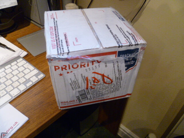
Is this part IV? Anyway. Box arrived.

SKF Speedi-Sleeves. Both the same. The come in a size range min to max measurement. These were just at the top end of the tolerance and I thought they might be pretty tight. But they are thin. I had to make a tool to knock them down the shaft and as luck would have it this water pipe was perfect. They were pretty snug and you could see them stretch as they went up the transition in the shaft onto the bearing surface. Pretty tidy.

You have to cut a nick in the skirt so that you can tear it off at the end. Here’s the sleeve fitted on the shaft

The skirt coming off and the finished repair. I tried a seal on it and it was fine.


Pretty fine this morning so next job was to put in the inner axle oil seals. I decided to machine my current universal tool to be a perfect fit for this job. Quick whizz in the lathe and it was done.

Perfect fit in the seal so that the edge is supported properly.

Couple of taps with the mallet and voilà, inner seal fitted. I didn’t stand them out at all given that I had just fitted repair sleeves to the shafts.


Time to get dirty. Much easier to pack the birfields without the shafts in.

It’s necessary to crush the snap ring to allow the shaft to pop into the CV. There is a knack to it. I sometimes use a jubilee clip but a tie wrap works really well in the field. Crush the snap ring, put the splines into the middle of the CV and give it one meaningful whack, with feeling. And the shaft should slip straight in. If it doesn’t then don’t go battering at it. Pull out, check and go again.


Whilst all greasy, I slathered up the new needle rollers and stuck the paper gasket on with a dab of grease too.

Back out side, I tapped in the new outer races for the swivel bearings. No mystery to this. Just tap them in. At this point I put the felt and rubber seals over the knuckle ready for later.

I also coated the back of the knuckles with grease as it’s really difficult to get it in there once assembled.

Mechanic I may be but engineer I ain’t but at this point I wanted too look at Frank’s thoughts on setting up the swivel housing. I went back to the FSM to see if there was any Voodoo in there. There wasn’t. Fit bearings, put shim in, tighten up. If preload too much, add some more shim. End of chapter.
So, I put the swivel on and placed a jack underneath the hub and took the bottom bearing up tight after torquing up the cone nuts underneath. When you do that properly, you really appreciate just how tight then should be.


I put the top cap on with the factory shim in and tapped it down into the bearing and put the bolts in but only got them as tight as I could BY HAND. There was no play in it, but there was also no preload at all.
Using feelers, I measured the gap under the cap. It was 0.47mm

I ran the bolts down and the gap closed completely but with minimal torque on the spanner. I measured the preload and it was absolutely cock on. Supposed to be 2.5 to 4.5 KG. I torqued the top cap and measured again. It was the same. Sweet.

So I have no idea what all that means, but all I can say is it all looked good, I followed the manual and the setting was correct. And I didn’t use the sort of force that I would have thought worrying. Now, where did the 0.47mm go? Some may just have been what I couldn’t do by finger and some might be swivel hub distortion.

I put the genuine wiper seals in.

Fiddly job.

And, whilst I was at it, I spotted what looked like a crack in the web between the axle and the steering arm stop. One site it made a nice heavy clack clack when I moved the steering full right and on full left the hub made a sort of dull thud. Hmm. So a bit of prep, out with the MIG, Bzzzzzzt. No crack.


Back on track. Now, at this point – I have to insert EDIT THREAD HERE.
The CVS, which I am now running backwards, are a bit of a weak point in the build. I need to get some new ones and it’ll probably have to be genuine ones. Ouch. So at this point, I have greased them up, packed the back of the hub and the swivel bearings but I have not packed the hub cavity full of CV grease as you should do. Simply because I will have to go back in there shortly. I am not planning a trip across the Moab in the next few weeks so this will just have to hang for now. Back soon. So save the hate mail, I have to be able to move the car off the drive.
Enough grease for now

Here’s the long shaft in place. I have to say this one put up a fight. I have done dozens of these and this one was a tricksy little blighter.

Stub axle on with paper gaskets, new dust ring and brake shield. Bolts set to 34 ft lbs


Then it went black. The sky flashed, hail came down, the dog hid and I made a cuppa.
SKF Speedi-Sleeves. Both the same. The come in a size range min to max measurement. These were just at the top end of the tolerance and I thought they might be pretty tight. But they are thin. I had to make a tool to knock them down the shaft and as luck would have it this water pipe was perfect. They were pretty snug and you could see them stretch as they went up the transition in the shaft onto the bearing surface. Pretty tidy.
You have to cut a nick in the skirt so that you can tear it off at the end. Here’s the sleeve fitted on the shaft
The skirt coming off and the finished repair. I tried a seal on it and it was fine.
Pretty fine this morning so next job was to put in the inner axle oil seals. I decided to machine my current universal tool to be a perfect fit for this job. Quick whizz in the lathe and it was done.
Perfect fit in the seal so that the edge is supported properly.
Couple of taps with the mallet and voilà, inner seal fitted. I didn’t stand them out at all given that I had just fitted repair sleeves to the shafts.
Time to get dirty. Much easier to pack the birfields without the shafts in.
It’s necessary to crush the snap ring to allow the shaft to pop into the CV. There is a knack to it. I sometimes use a jubilee clip but a tie wrap works really well in the field. Crush the snap ring, put the splines into the middle of the CV and give it one meaningful whack, with feeling. And the shaft should slip straight in. If it doesn’t then don’t go battering at it. Pull out, check and go again.
Whilst all greasy, I slathered up the new needle rollers and stuck the paper gasket on with a dab of grease too.
Back out side, I tapped in the new outer races for the swivel bearings. No mystery to this. Just tap them in. At this point I put the felt and rubber seals over the knuckle ready for later.
I also coated the back of the knuckles with grease as it’s really difficult to get it in there once assembled.
Mechanic I may be but engineer I ain’t but at this point I wanted too look at Frank’s thoughts on setting up the swivel housing. I went back to the FSM to see if there was any Voodoo in there. There wasn’t. Fit bearings, put shim in, tighten up. If preload too much, add some more shim. End of chapter.
So, I put the swivel on and placed a jack underneath the hub and took the bottom bearing up tight after torquing up the cone nuts underneath. When you do that properly, you really appreciate just how tight then should be.
I put the top cap on with the factory shim in and tapped it down into the bearing and put the bolts in but only got them as tight as I could BY HAND. There was no play in it, but there was also no preload at all.
Using feelers, I measured the gap under the cap. It was 0.47mm
I ran the bolts down and the gap closed completely but with minimal torque on the spanner. I measured the preload and it was absolutely cock on. Supposed to be 2.5 to 4.5 KG. I torqued the top cap and measured again. It was the same. Sweet.
So I have no idea what all that means, but all I can say is it all looked good, I followed the manual and the setting was correct. And I didn’t use the sort of force that I would have thought worrying. Now, where did the 0.47mm go? Some may just have been what I couldn’t do by finger and some might be swivel hub distortion.
I put the genuine wiper seals in.
Fiddly job.
And, whilst I was at it, I spotted what looked like a crack in the web between the axle and the steering arm stop. One site it made a nice heavy clack clack when I moved the steering full right and on full left the hub made a sort of dull thud. Hmm. So a bit of prep, out with the MIG, Bzzzzzzt. No crack.
Back on track. Now, at this point – I have to insert EDIT THREAD HERE.
The CVS, which I am now running backwards, are a bit of a weak point in the build. I need to get some new ones and it’ll probably have to be genuine ones. Ouch. So at this point, I have greased them up, packed the back of the hub and the swivel bearings but I have not packed the hub cavity full of CV grease as you should do. Simply because I will have to go back in there shortly. I am not planning a trip across the Moab in the next few weeks so this will just have to hang for now. Back soon. So save the hate mail, I have to be able to move the car off the drive.
Enough grease for now
Here’s the long shaft in place. I have to say this one put up a fight. I have done dozens of these and this one was a tricksy little blighter.
Stub axle on with paper gaskets, new dust ring and brake shield. Bolts set to 34 ft lbs
Then it went black. The sky flashed, hail came down, the dog hid and I made a cuppa.
Attachments
Red Oktober
Well-Known Member

Nice job Chris ...

Inspirational to see method, precision and clean working, in action Chris. There are two ways to do a job!

- Joined
- Nov 19, 2010
- Messages
- 6,242
- Country Flag
Although this isn't LC it is related via the Speedy sleeve item as I have been rebuilding the Trol front axle due to the ingress of sand and mud the stub axle was scored where the hub seal is in contact so a Speedy Sleeve was the answer.

I fitted it with an old damper cover off a Lotus Elan

Then had it machined down the village to suit.

Andy

I fitted it with an old damper cover off a Lotus Elan

Then had it machined down the village to suit.

Andy
That's neat! You must be pleased with that Andy
- Joined
- Nov 19, 2010
- Messages
- 6,242
- Country Flag
Yes I an Clive, the stub axles were in a bit of a mess but they should be good now. I've been using these for years, especially on HGV rear axle cases but I have used them on other things.
( I think this tangent needs transfering to my other thread about the Trol.)
Andy
( I think this tangent needs transfering to my other thread about the Trol.)
Andy