- Joined
- May 13, 2014
- Messages
- 744
- Country Flag
I've set this out in two sections for easy reading, theory and practice. It's just what I learned, if there are errors let me know and I'll update this.
THE THEORY
On the assembly which has the large and small gear, there are two springs. These springs are referred to as ‘waiting springs’.
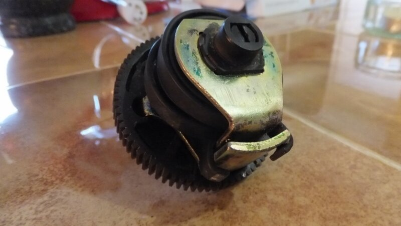
As I understand it, when you engage or disengage the diff lock, the electric motor does its thing and turns the big gear. If the locking mechanism in the diff is all aligned, the shaft moves and the small gear turns, moving the shaft out or in to to engage or disengage the lock …. perfect. However, if it’s not all aligned, the shaft can’t move so the motor still does its thing and turns the gear, but this time the springs are wound up. By design, the electric motor will stop turning at the required point transferring the energy into the springs. When things do line up in the diff, the energy in the springs drives the small gear engaging or disengaging the lock as required.
Note:- Don’t take this assembly apart unless something is broken, there shouldn’t really be any need. If you do, you will have to wind up the springs again and your guess is as good as mine as how much this should be done by.
Look at the underside of the assembly and you will see that there is a shiny metal plate with two plastic areas in it.
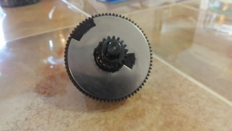
This is in essence a switch. As the gear rotates, the 3 spring contacts screwed on the bottom of the housing make contact when on metal and break contact when on the plastic. This action starts and stops the motor and of course reverses the motor to lock (or unlock depending on your perspective here). So, if you had the right “Reference Points” you could continuously check the continuity in the circuits to determine the on position and the off position for each direction of rotation (i.e. in or out). In doing this the shaft will move in or out and if you had the Dimensions you could set this up.
The Reference Points you need are:
The Dimensions you need are: The diff is unlocked when the shaft sticks out 55.5mm and locked when it sticks out 73mm. Visually, it looks like this:
Unlocked - - - - - - Mid Point - - - - - - Locked
55.5 63 73
The Terminals you need to check continuity are as follows: with the locking part of the connector at the top the top row of pins are numbered 3, 2 and blank. The second row is 4, 5 and 6. Pins 4 and 5 test retraction, 4 and 6 test extension. 4 is black, 5 is yellow, 6 is green.
PRACTICE
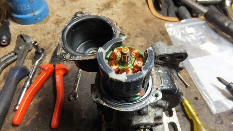
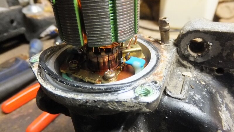
To recap, you now have the armature in the housing and the brushes properly seated. From this point on, keep an eye on the armature as during the following it may pop out and you’ll have to re-seat the brushes again which after 3 or 4 times becomes a right PITA, believe me
Step1
Grease up and insert the locking shaft into the housing. You need to align this so it sticks out of the housing to the Mid Point, i.e. 63mm. By doing this, the ridges on the shaft which are now on the inside are roughly in the right position. Remember, what happens when you apply electricity is that the shaft moves in or out and it is this that we are now trying to set correctly. If you set it up so it sticks out less than this then on full retraction the inside end of the shaft will collide with housing when the motor is running. This will damage your motor, gears or both. Conversely, if you set it up too long then on full extension, the shaft may come out.
Step 2
Take the assembly and while looking at the shiny plate on the large gear, find the Mid Point between the two plastic areas. Now, draw a mark on the opposite side of the large gear in a place which matches this Mid Point. This is so you can see it when the assembly is installed.
Step 3
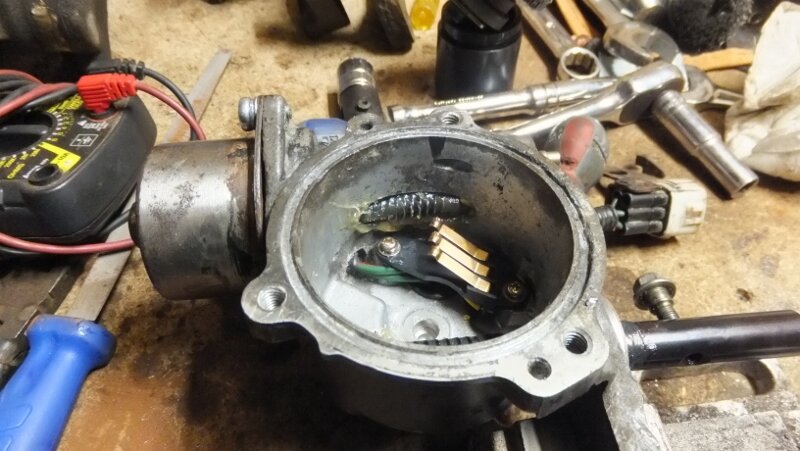
You need to know where the 3 contacts are when the assembly is installed, so take a marker pen and on the inside of the housing draw a line up from the contact to the top. In the pic below you can see an arrow head pointing down .....
Step 4
Take the assembly and line up the mark you made in step 2 with the mark you made in step 3 and lower the assembly so both gears engage. Your assembly is now roughly aligned and it’s time to test how close it is.
Step 5 – test retraction
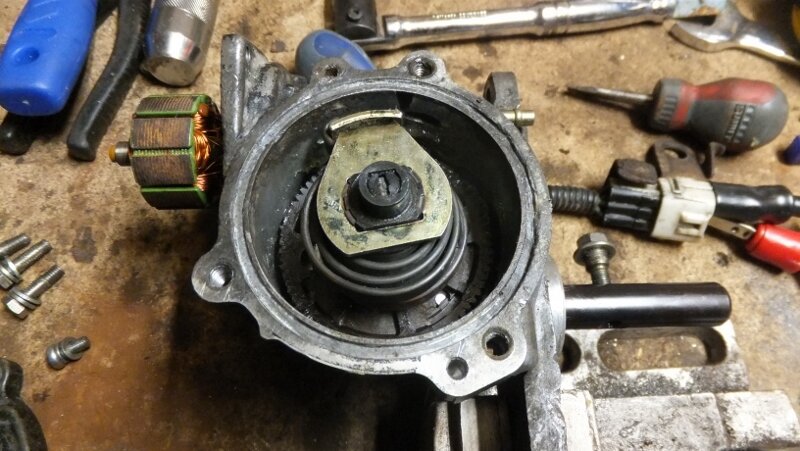
Put the cover over the assembly and locate it on its dowels. Connect your meter to pins 4 and 5. My tester gives an audible beep when there is continuity. It sounds straight away. Rotate the armature spindle so the locking shaft retracts. Keep rotating until continuity is lost or the shaft is sticking out 55.5mm or so. If it reaches 55 and is still sounding, you need to rotate the large gear on the assembly round a tooth and re-test. Repeat until the sound stops when 55mm is reached. Don’t worry about the odd half millimetre !!! This is what it looks like once done and the cover is removed.
Step 6 – test extension
Repeat the above but turning the armature the other way and using pins 4 and 6. It is likely that you will not need to adjust further at this point as it is the start point which determines the extension because the shiny plates tells the motor when to stop winding out.
If you’ve done all the above, you should have a working Diff Lock
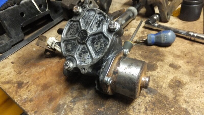
go and connect it to the car and test it
Hope this helps

THE THEORY
On the assembly which has the large and small gear, there are two springs. These springs are referred to as ‘waiting springs’.

As I understand it, when you engage or disengage the diff lock, the electric motor does its thing and turns the big gear. If the locking mechanism in the diff is all aligned, the shaft moves and the small gear turns, moving the shaft out or in to to engage or disengage the lock …. perfect. However, if it’s not all aligned, the shaft can’t move so the motor still does its thing and turns the gear, but this time the springs are wound up. By design, the electric motor will stop turning at the required point transferring the energy into the springs. When things do line up in the diff, the energy in the springs drives the small gear engaging or disengaging the lock as required.
Note:- Don’t take this assembly apart unless something is broken, there shouldn’t really be any need. If you do, you will have to wind up the springs again and your guess is as good as mine as how much this should be done by.
Look at the underside of the assembly and you will see that there is a shiny metal plate with two plastic areas in it.

This is in essence a switch. As the gear rotates, the 3 spring contacts screwed on the bottom of the housing make contact when on metal and break contact when on the plastic. This action starts and stops the motor and of course reverses the motor to lock (or unlock depending on your perspective here). So, if you had the right “Reference Points” you could continuously check the continuity in the circuits to determine the on position and the off position for each direction of rotation (i.e. in or out). In doing this the shaft will move in or out and if you had the Dimensions you could set this up.
The Reference Points you need are:
- The location of the 3 contacts (hidden when the assembly is installed)
- The Mid Point between the two plastic areas in the shiny metal plate mentioned above (also hidden when the assembly is installed)
The Dimensions you need are: The diff is unlocked when the shaft sticks out 55.5mm and locked when it sticks out 73mm. Visually, it looks like this:
Unlocked - - - - - - Mid Point - - - - - - Locked
55.5 63 73
The Terminals you need to check continuity are as follows: with the locking part of the connector at the top the top row of pins are numbered 3, 2 and blank. The second row is 4, 5 and 6. Pins 4 and 5 test retraction, 4 and 6 test extension. 4 is black, 5 is yellow, 6 is green.
PRACTICE
To recap, you now have the armature in the housing and the brushes properly seated. From this point on, keep an eye on the armature as during the following it may pop out and you’ll have to re-seat the brushes again which after 3 or 4 times becomes a right PITA, believe me
Step1
Grease up and insert the locking shaft into the housing. You need to align this so it sticks out of the housing to the Mid Point, i.e. 63mm. By doing this, the ridges on the shaft which are now on the inside are roughly in the right position. Remember, what happens when you apply electricity is that the shaft moves in or out and it is this that we are now trying to set correctly. If you set it up so it sticks out less than this then on full retraction the inside end of the shaft will collide with housing when the motor is running. This will damage your motor, gears or both. Conversely, if you set it up too long then on full extension, the shaft may come out.
Step 2
Take the assembly and while looking at the shiny plate on the large gear, find the Mid Point between the two plastic areas. Now, draw a mark on the opposite side of the large gear in a place which matches this Mid Point. This is so you can see it when the assembly is installed.
Step 3
You need to know where the 3 contacts are when the assembly is installed, so take a marker pen and on the inside of the housing draw a line up from the contact to the top. In the pic below you can see an arrow head pointing down .....

Step 4
Take the assembly and line up the mark you made in step 2 with the mark you made in step 3 and lower the assembly so both gears engage. Your assembly is now roughly aligned and it’s time to test how close it is.
Step 5 – test retraction
Put the cover over the assembly and locate it on its dowels. Connect your meter to pins 4 and 5. My tester gives an audible beep when there is continuity. It sounds straight away. Rotate the armature spindle so the locking shaft retracts. Keep rotating until continuity is lost or the shaft is sticking out 55.5mm or so. If it reaches 55 and is still sounding, you need to rotate the large gear on the assembly round a tooth and re-test. Repeat until the sound stops when 55mm is reached. Don’t worry about the odd half millimetre !!! This is what it looks like once done and the cover is removed.

Step 6 – test extension
Repeat the above but turning the armature the other way and using pins 4 and 6. It is likely that you will not need to adjust further at this point as it is the start point which determines the extension because the shiny plates tells the motor when to stop winding out.
If you’ve done all the above, you should have a working Diff Lock

go and connect it to the car and test it
Hope this helps


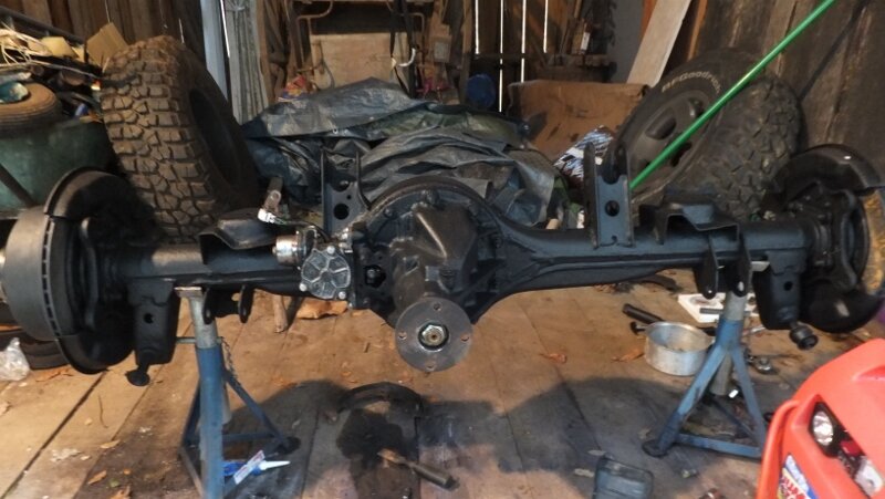
 ...... time flies.