Cptsideways
Well-Known Member
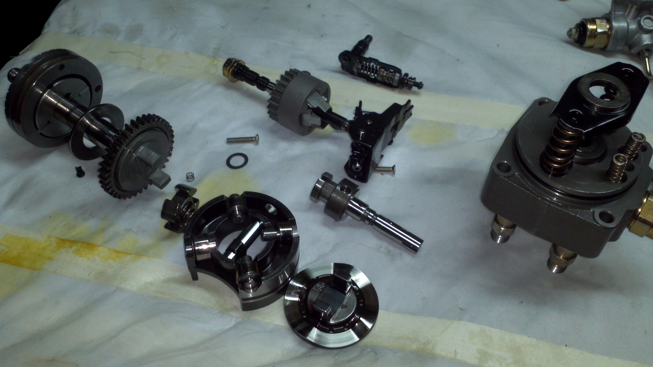
I have spent the past week (or so) playing with Bosch VE fuel pumps, the same as fitted to 80's (though they are Jap built Zexel's I think) & I now know all about their inner workings 
I am building a "hybrid" pump for my Hymer camper as my god it's slow, 90bhp allegedly from a POS Lucas CAV pump, I think its nearer 50bhp if I'm honest so its going in the bin & being converted to the VE pump which is being built up from various other pumps to get the right selection of parts.
There a few things which will help with making em go.
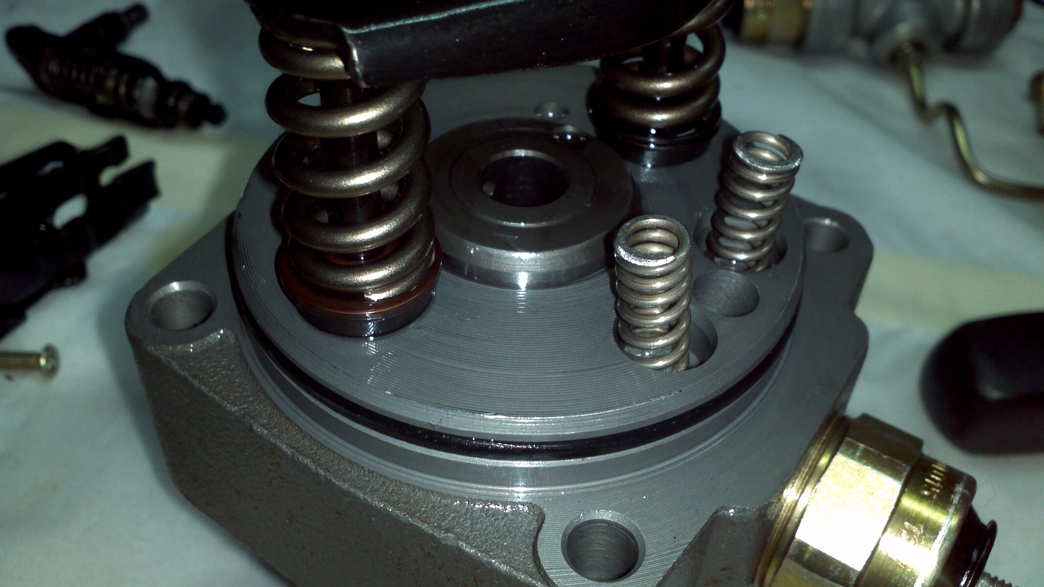
Main thing is plunger size & I'm guessing the LC has a big 14mm one to start with ? Usually this is upgrade'able with a bigger hydraulic head but the LC might have a big one to start with. If it is this is pretty simple & a massive upgrade, I'm guessing the Yanmar marine applications use a bigger plunger & head for their 300hp.
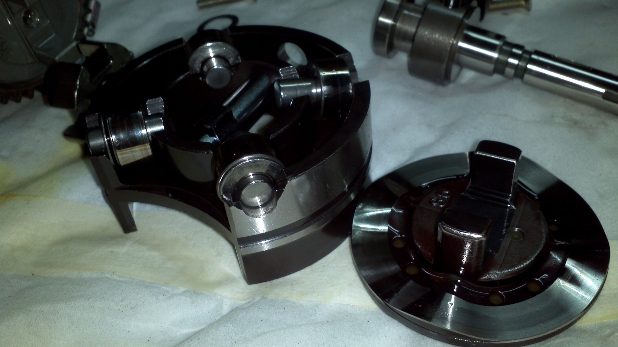
Next is the camplate that operates the plunger, bigger ones give more squirt
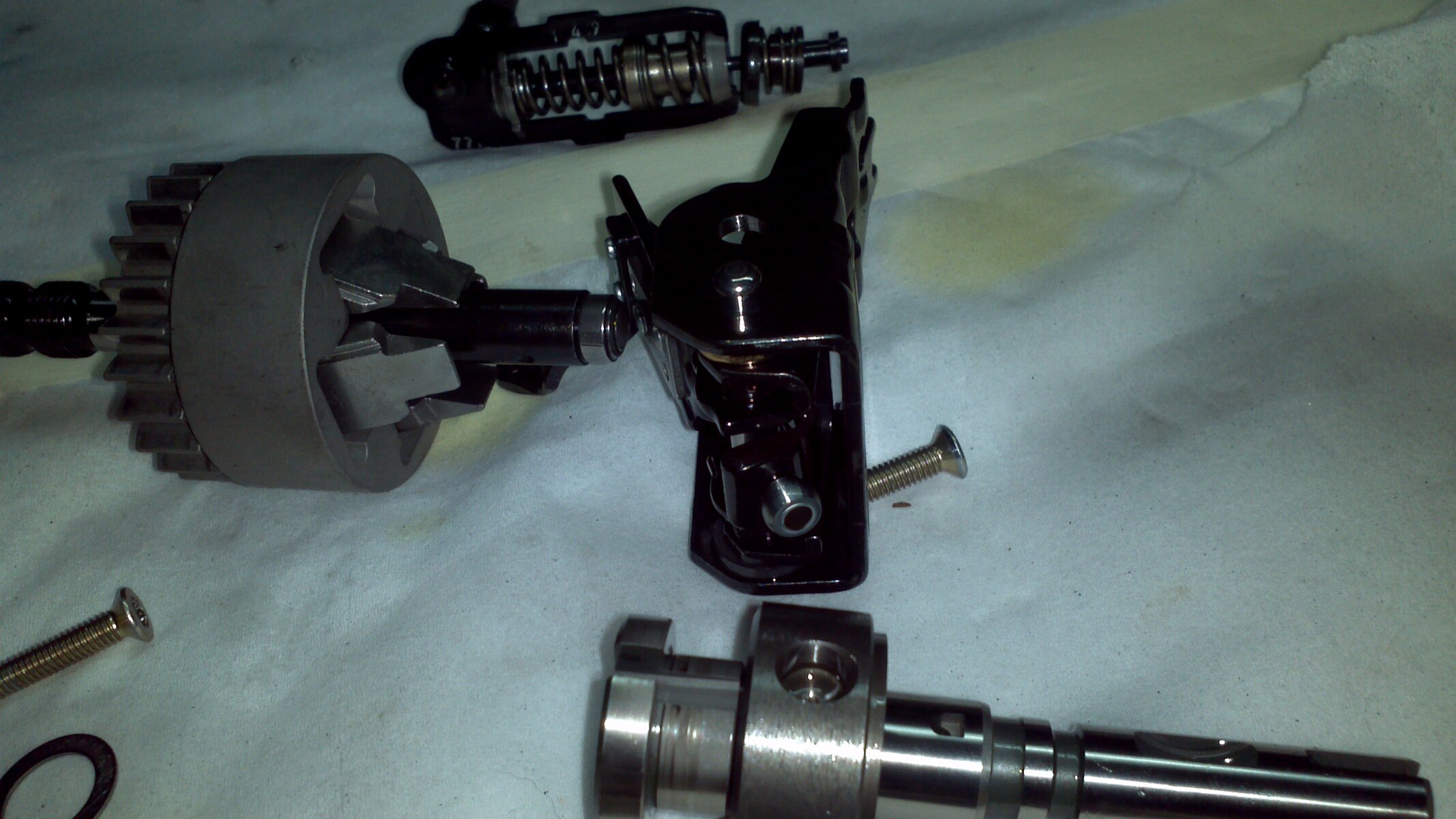
Then we have governors & springs, the springs are the bit that are tweakable & react against the Governor
The main rack screw just moves the whole lot further along like giving it more throttle to start with, its only connected to the governor anyways. And the Governor just operates the simplest bleed off valve from the plunger to give throttle variation.
Lastly & this appears to the sneaky one, there is a pressure relief valve for the casing, its normally fixed but they are rather simple to tweak! This is also related to those who have added a booster pump it will have a similar effect to a degree.
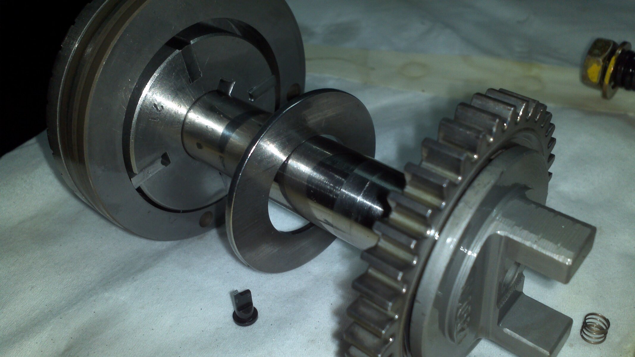
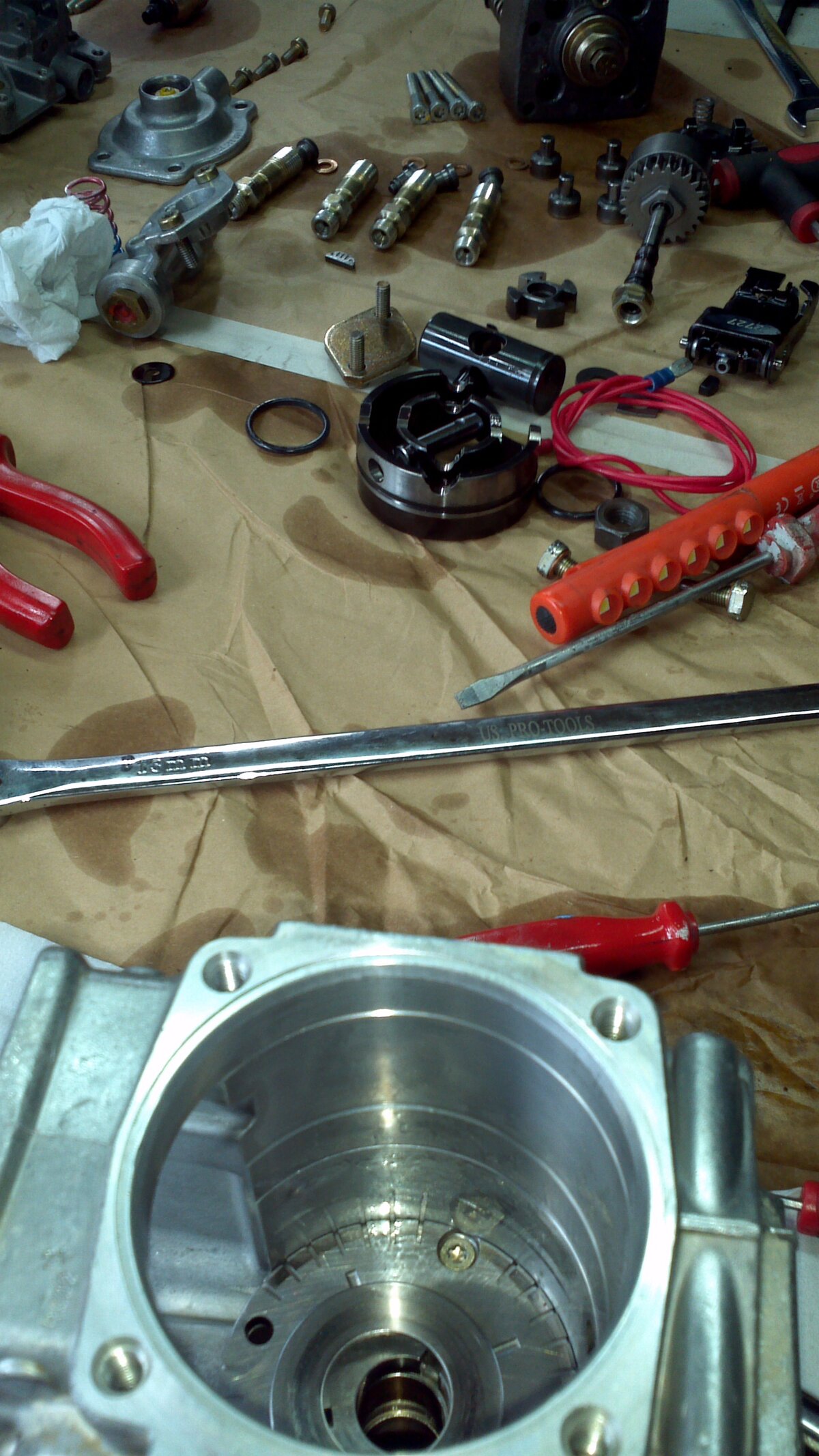
The inner workings of a VE Pump revealed, its actually really simple once you get your head round it. Though 160 individual parts simple!


