Don't like the adverts?  Click here to remove them

Hedgehog - LC100 build thread

Also selected the water purification and filtration system to use. I will use the Nature Pure Seagull IV X-1B model which comes without faucet. I will just have a simple outlet pipe and tap. This model is small enough to mount under the drawer side wings along with the pump and water metering/counter, hoses and electrics. This one is a job for next month......

Seagull_IV_X_1B_4db01644b32d4.jpg


http://www.purewateronline.co.uk/700008-X-1B-Seagull-R-IV-Basic.html
 
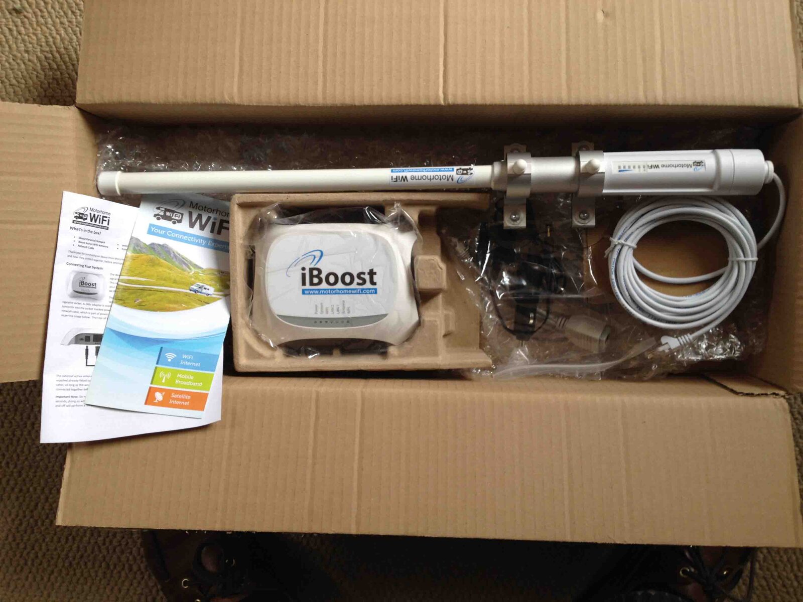
WiFi range extender/router arrived today. Got it configured OK but had a weird tech problem caused by interference from the Apple Airport (in my house) affecting the high gain antenna. Tech support spotted it in a few seconds so was no problem.

Anyway the system works fine. Easy to set-up, good instructions, user friendly. The list of WiFi SSDs detected was enormous (looks like the whole of my village!) so bodes well for piggy-backing on some free wifi in campsites, bars etc

IMG_1413 low res.jpg

I need to think of a way to lay down the antenna to protect from low branches etc as it is not bendy like a whip aerial. It is only about 18" long tip to tip, with the antenna 12" of that. It can be mounted to a window using the 4 suckers (internal or external) and just wheeled out when required but external operation up high will give best performance. Perhaps something like a long garage door hinge and a drop bolt to lock in position will do it?
 
Steve, does the Glind system have a thermostat?
 
The system is controlled by the dash heater controls primarily but you can tweak it by adjusting/restricting flow and with a mixer valve if that the way you want to go.

Its normally plumbed in after the hot/cold diverter valve for the heating system. I am sure Steve will have a better explanation or at least more detail. I have the Helton system waiting to go in my 80 when i get to SA.

Warren - I wish I shared your confidence in my ability :). In terms of thermostatic control I plan to suck it and see first. Chief amongst these is the flow rate adjustment vs engine heat. Potentially could add a thermostatic limiter valve like those used in hospitals and nursing homes....if overheat is a problem (which I doubt). I will report back as I get to see how the thing operates. There is no inbuilt stat. If I get it sorted before Lincomb then I'll be offering demos :)
 
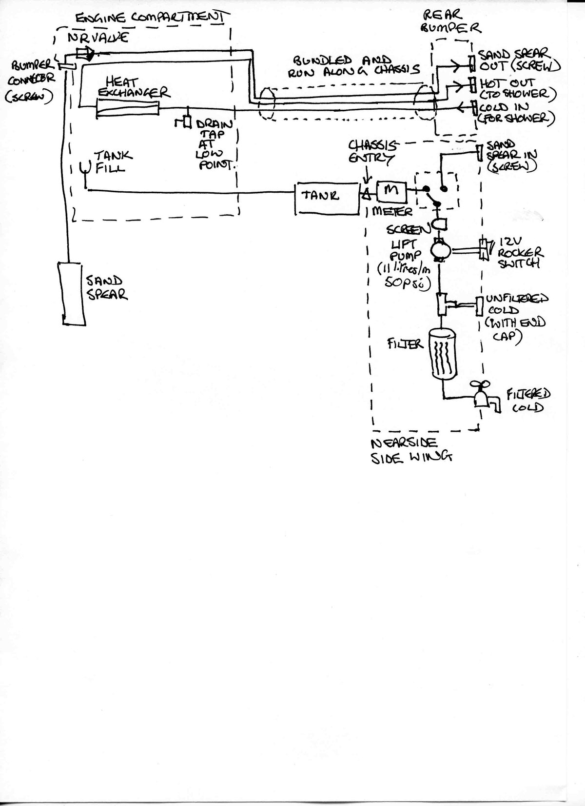
I've put the water and shower system schematic diagram below - any comments gratefully received.

The design aim for this was to:
keep the design a simple as possible; allow the shower to be fed from the tank or the sand spear; try to keep the pipes installed in/on the vehicle where possible so there is less faff with running hose-line out when we set up; try to minimise use of diverter valves; keep entry/exit points into the vehicle chassis to a minimum; try to keep the controls/inputs/outputs to the rear of the vehicle; single pump/strainer to power both shower and water purification systems

I'm hoping to use the rear ARB bumper to house a input/output connection point, with the opposite connections largely being mounted along with the pump and filter under the side wing on the drawer system
Land Cruiser Water Shower Schematic.jpg
I think there is sprobably at least one further simplification I can make which is not to have the run to the front bumper for the sand spear line, but just to run that direct from the rear when I need to.

Pipes on the 'suck' side are recommended to be threaded rather than garden hose push fit variety so as to not suck in air. Pipes have to be firm walled too.

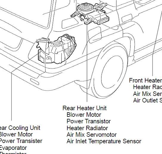
I need to check to see whether the heater matrix for the rear ventilation could potentially be used as a pick off for the heat exchanger water feed pipes - this would shorten the runs to/from the heat exchanger. If anyone has experience of this area then please let me know

Land Cruiser Rear Heater Position.jpg
 
Don't like the adverts?  Click here to remove them
Maybe I am looking at it wrong Steve but there is no pump to push the water through the heat exchanger? Or if there is i cant see how it attaches to the unit.
 
Maybe I am looking at it wrong Steve but there is no pump to push the water through the heat exchanger? Or if there is i cant see how it attaches to the unit.

Sorry Warren, I didn't explain the principle that well. The heat exchanger is fed by the pump by connecting a short section of hose from the "Unfiltered Cold" to the "Cold In for Shower". Just saves drilling another set of holes in the truck for the sake of 3ft of garden hose and allows the diverter valve to put tank water to the shower or the filter.

The rear heater matrix looks a good candidate to tap off for the shower heat exchanger from what I can see...I need to get under the truck at the weekend and take a look. Does anyone know if there is a constant (or regulated) feed direct from the engine or is there a switched valve selected only when the "Rear Fan" is switched on?? If those two pipes enter the body shell sensibly then I could tap off inside the truck - might be a quite elegant solution. Might even get rid of the rear heater matrix/fan assy altogether and save some weight into the bargain
 
The Rear Heater blower is not really rear as much as its middle. It sits under the passenger seat as an fyi and the rear cooling unit is plumbed intot he AC system which you can block off and remove if you want but I think its a nice to have and it has new lines running to it on your car as i did they.
 
The Rear Heater blower is not really rear as much as its middle. It sits under the passenger seat as an fyi and the rear cooling unit is plumbed intot he AC system which you can block off and remove if you want but I think its a nice to have and it has new lines running to it on your car as i did they.

I think keeping the rear air con is a must where we're going so I'll not disturb that (especially as someone went to a lot of trouble to fix the pipes :whistle: )...only the heater under the seat. I'm guessing the 2nd heater matrix feed pipes come into the vehicle shell rather than the heater matrix connections poking out through the floor - thoughts? Do you know if they are metal or rubber pipes under the truck/through the floor to the heater??
 
Steve, does the Glind system have a thermostat?

I can only have a shower from my 100 once the engine has cooled down, simply too much heat. The car heater control proved quite unsatisfactory for temp control.
There are things called 'tempering valves' which will allow you to regulate the heat better. Basically its a temperature sensitive valve with hot and cold in and warm out. It automatically mixes cold into the hot flow to prevent scolding, in a 4x4 its basically partially bypassing the Glind.
Engine coolant generally runs between 70–105°C depending on how long and how hard it has been driven. Believe me, the temp that the Glind can output can be very high.
If you use the flow control on the shower head and momentarily halt the flow, the Glind temp will rise rapidly and give you a bit of a shock when you restart the flow.

Most of these things are made for fairly high pressure so you need to choose one that operates at what your pump can put out.
http://www.nefa.com.au/our-products/tempering-valves.aspx

That's the sort of thing I had in mind re: as used in hospitals and nursing homes....got one in my house :)

But it needs a cold feed too, which means splitting the cold input line to have a line that bypasses the heat exchanger and goes to the valve....should be easy to rig up. I had in mind to use the main heater matrix to divert some of the engine heat/hot water volume if need be...I think will work the same but would be more troublesome to make balance hot/cold as it is effectively sucking heat out.

Tim at Glind doesn't recommend using the rear heater pick off point as it (apparently) doesn't have good results on heat output (see the other post on this subject here) but if the problem is overheat then this could be a useful alternative approach to tone down the heat

http://www.landcruiserclub.net/forums/showthread.php/50206-Heat-exchanger/page3
 
IMG_1444 low res.jpg

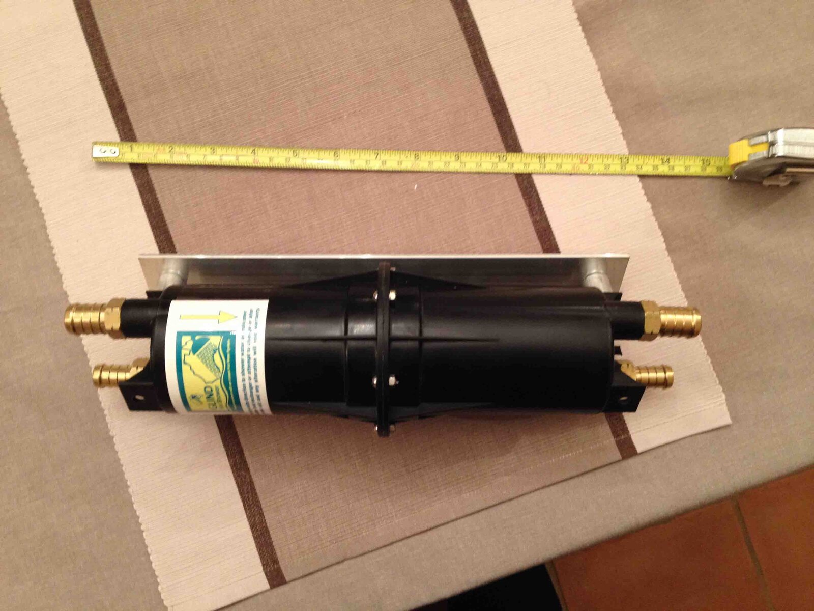
This week has been about finalising the water/shower system design and ordering and receiving the parts. The Glind heat exchanger and sand spear have been received from Australia (about 1 week end to end) and the other parts are beginning to arrive. The whole water system has been hard work to design....mainly because plumbing is a bit outside of my comfort zone and because there are so many different aspects to consider. I have taken on-board comments about maintaining a constant temperature for the shower and reports of the water being too hot (running engine) and have incorporated a temperature control element (a "TMV2" unit) hopefully to help with managing the heat output. This is a pretty big experiment so it will be interesting to se if it all works. The unit I've chosen is able to deal with the relatively high water temperatures that could result from the engine coolant (up to 82C) which is a way beyond the home heating system limit of 60-ish C. Taking advice from Tim @ Glind I will initially tap the HE into the main hot water circuit in the engine bay: I may later make use of the rear heater circuit after a suck/see period. The time consuming issue has been to sort out the various connectors/pipes and mountings for the different elements.....I'll post up a modified schematic for the water/shower system

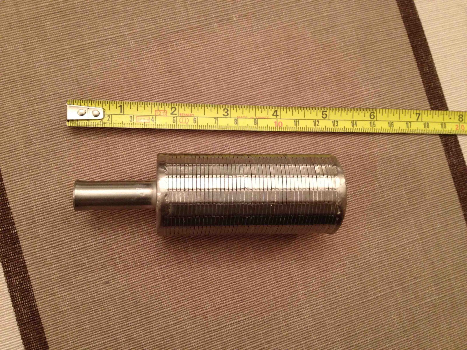
The sand spear is smaller than I expected. It is a stainless steel cylinder with some narrow cuts to sieve water through.

IMG_1445 low res.jpg
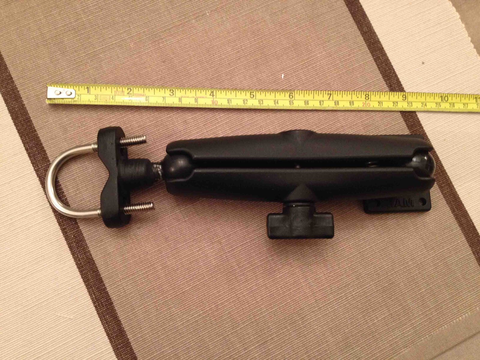
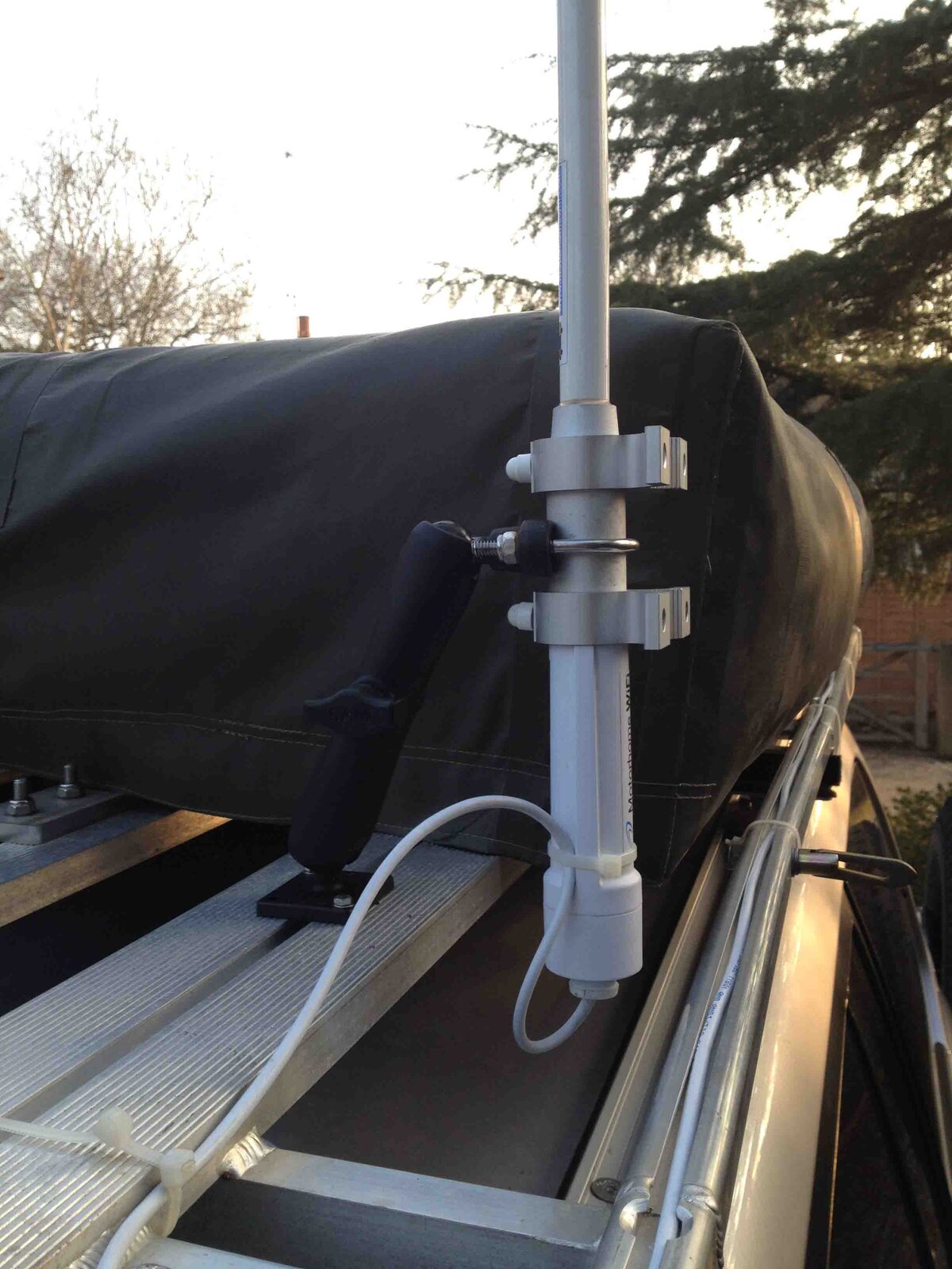
Also this week I have finalised the design for the WiFi antenna mounting - I have used a RAM mount as it is flexible and robust. It will be simple to put up the antenna when we need to. However, some very rough testing suggests that the position of the antenna has very little bearing on the signal receive strength but I will conduct some more testing over the next few months and report back. Realistically it may be that the antenna can be fixed to the roof rack laying down with little compromise to performance

IMG_1446 low res.jpg
 
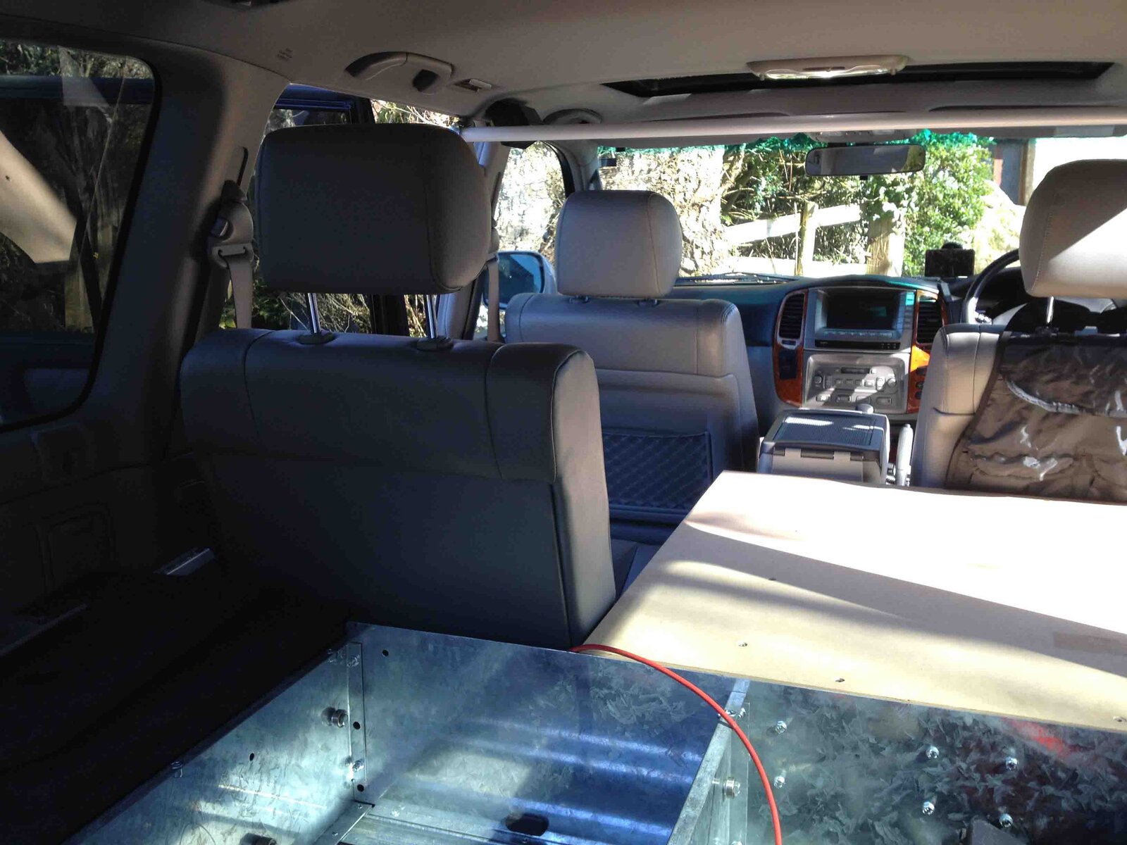
Installed the front floor/base extension today. This will allow us to sleep in the truck in emergency if we need to. It is designed to provide a continuous flat surface from the drawer system through to just behind the front seats. I have designed it in two parts to allow the 3rd seat to be retained if I want. This part replaces the 60% 2nd row seats. The base unit makes use of the existing seat mounting points rather than make more holes in the floor pan and also mounts to the Black Widow drawer system.

Initial impressions are that it is very rigid/stable and easily accepts a full body weight on it. Plenty of storage space under and options to add tie down points to the sides/back for the fridge. I may also put some aero tracking down so that I can strap loose items securely

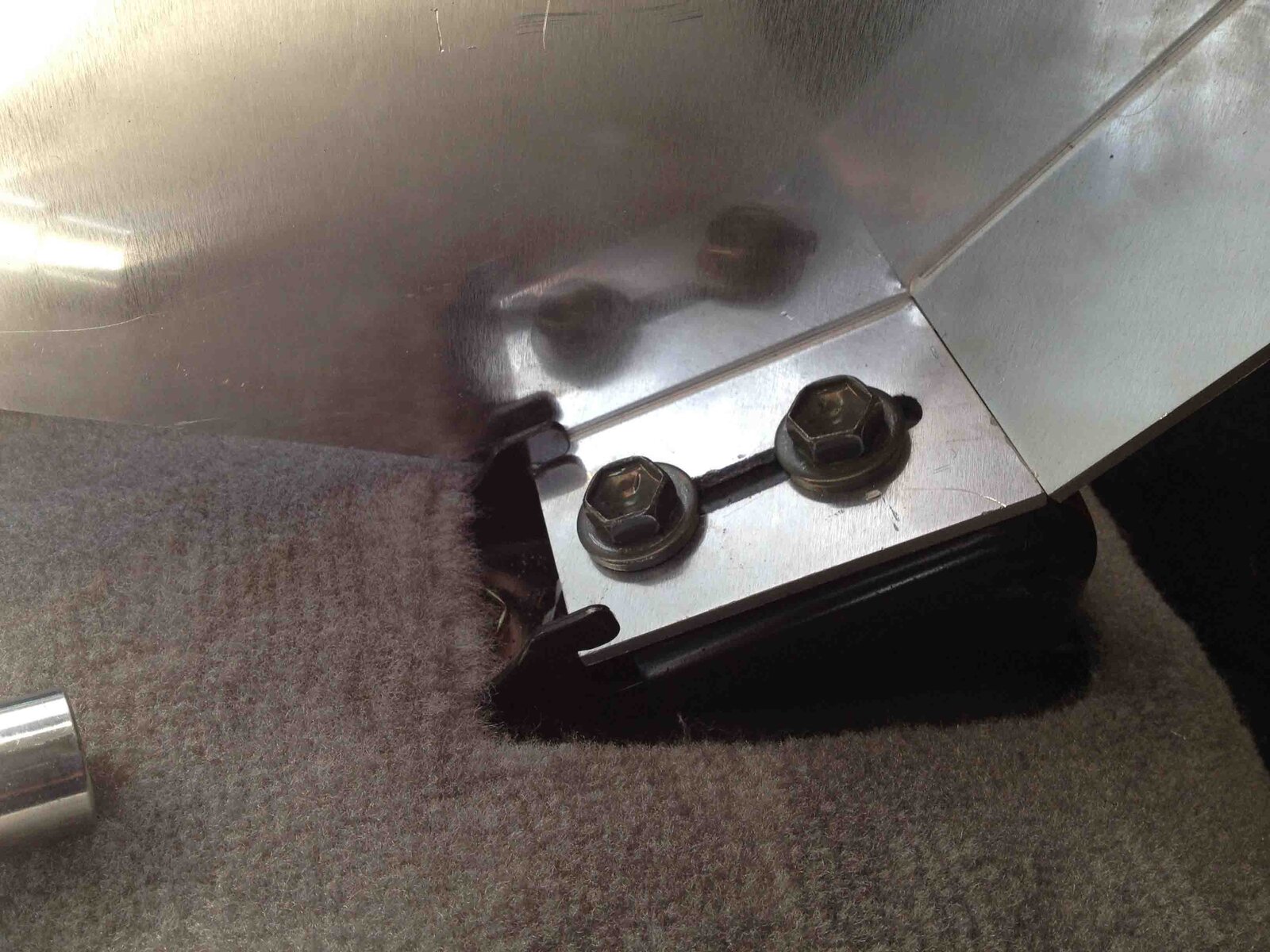
The mounting points to the original seat mounts
IMG_1464 low res.jpg

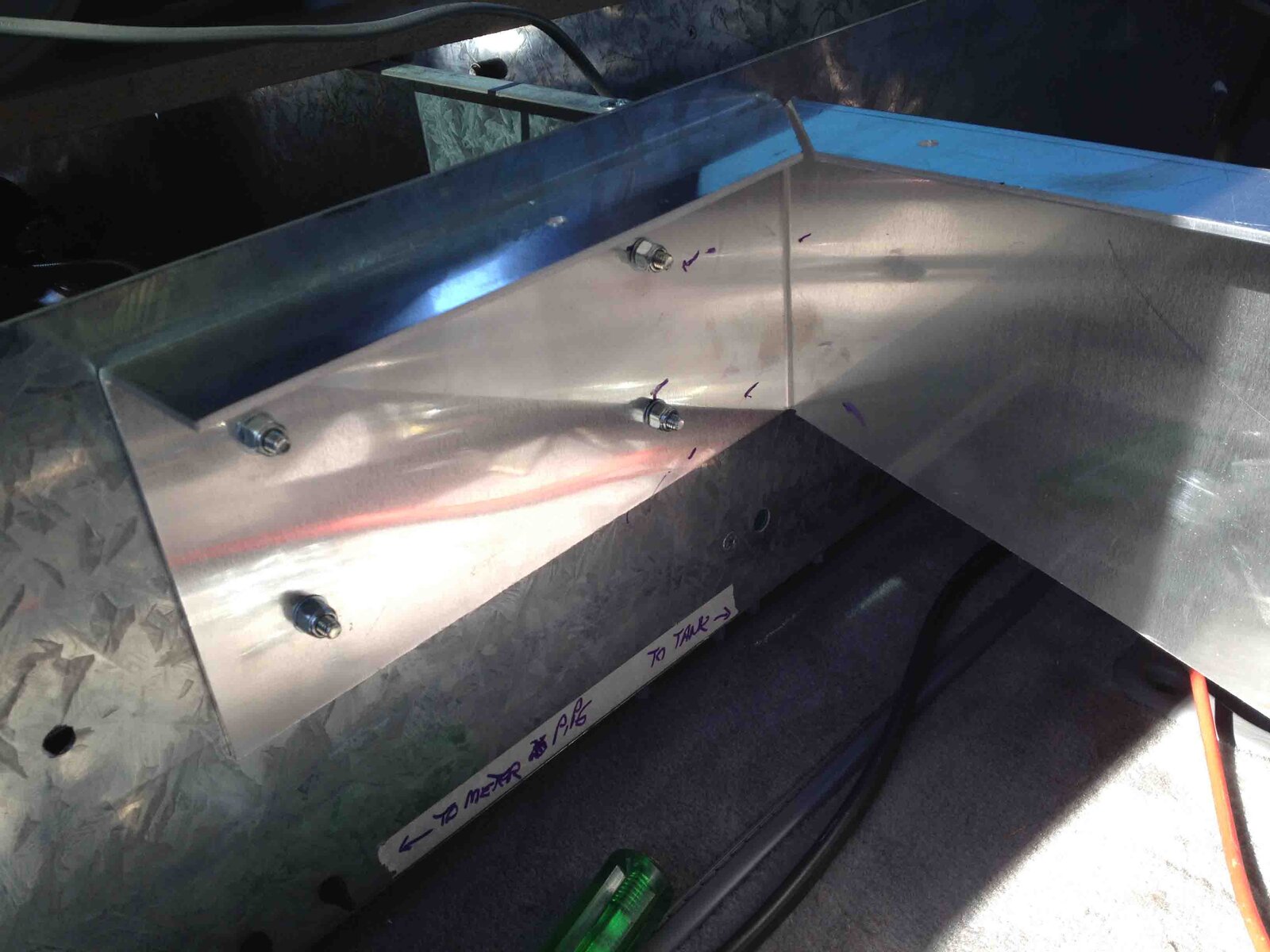
Mounting to the drawer rear plate
IMG_1465 low res.jpg

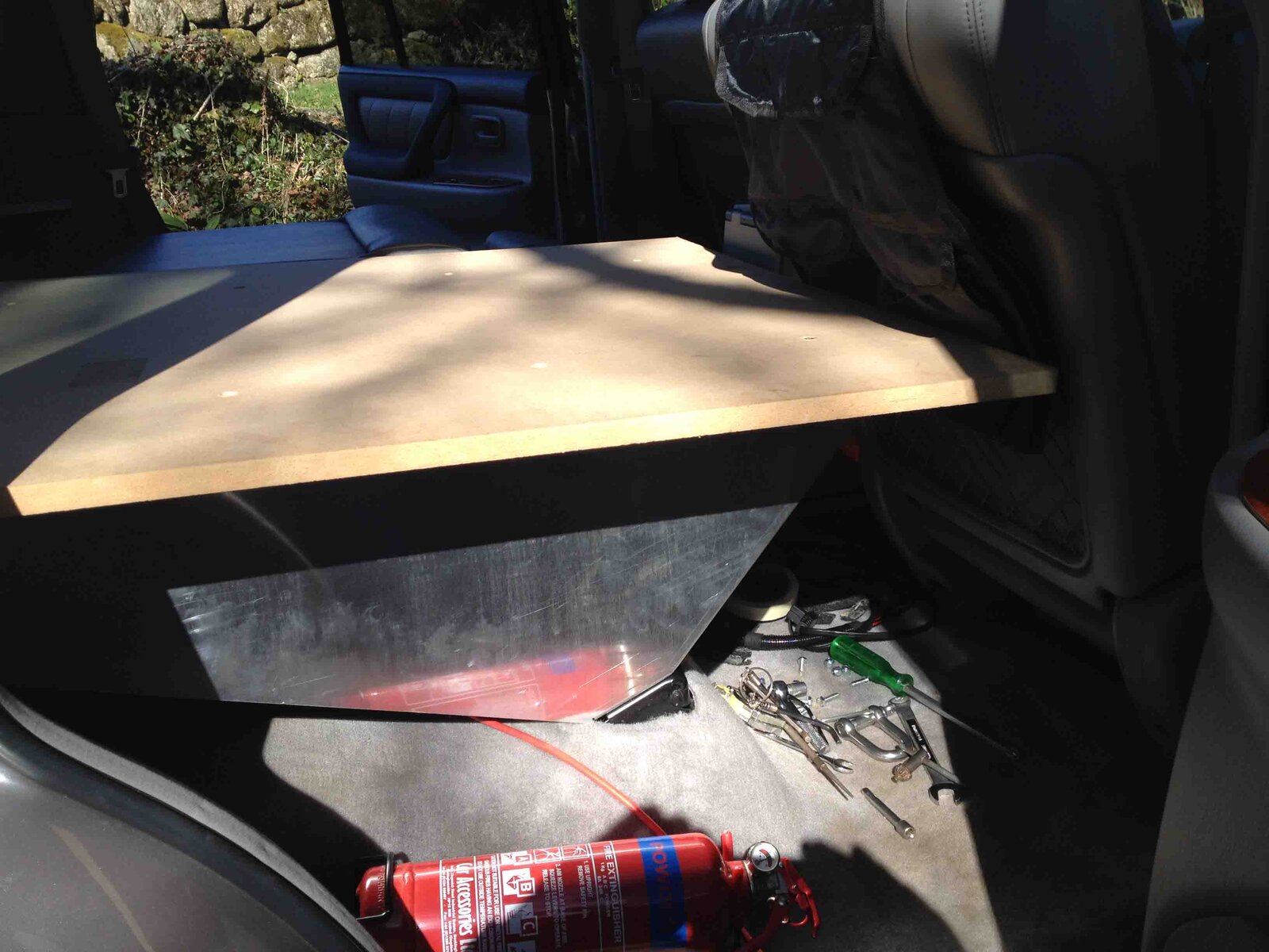
Side view of the supporting web/side plate
IMG_1466 low res.jpg


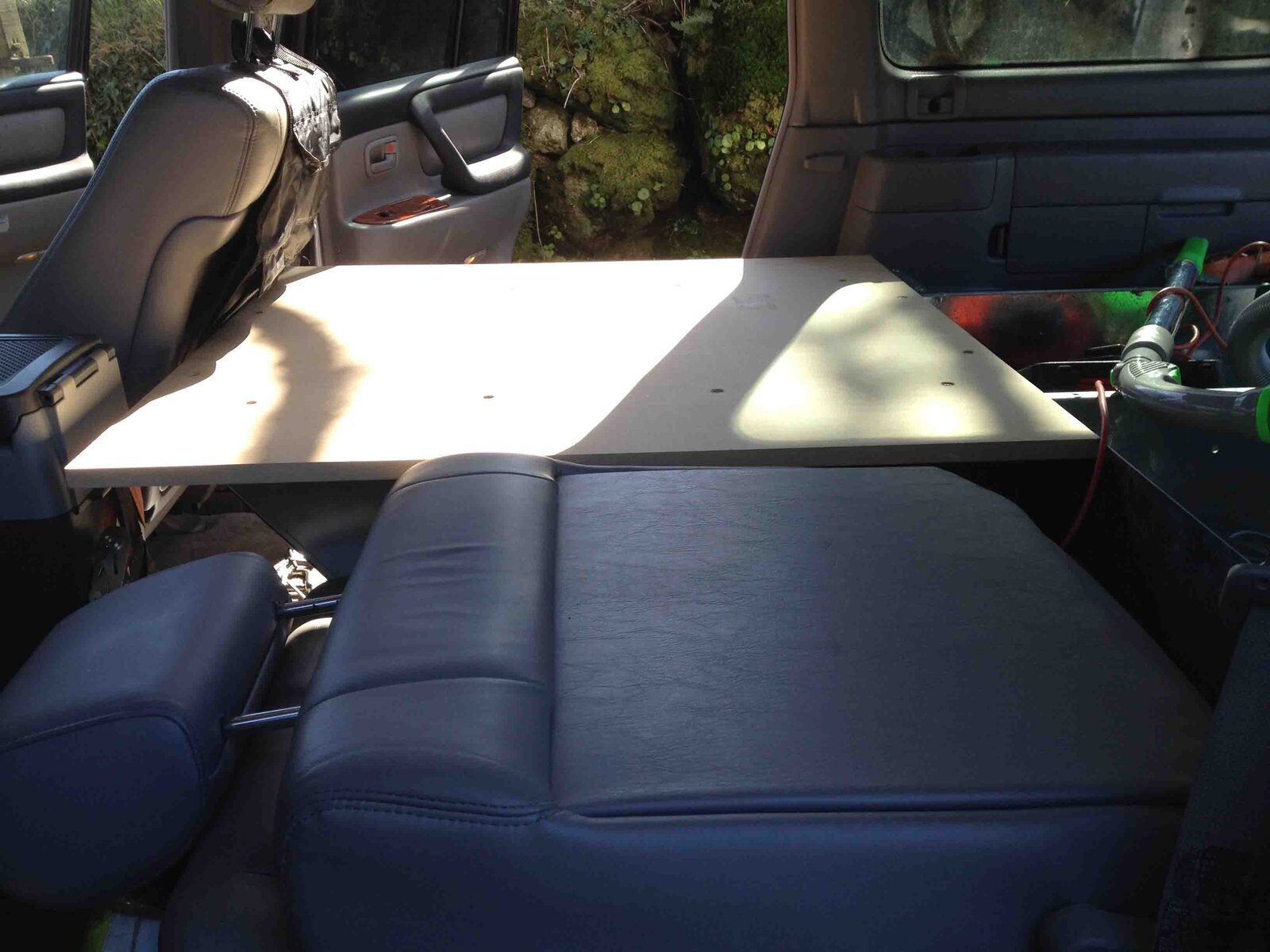
The top surface sits in line with the folded down 40% seat so that we can still sleep if the 3rd seat is fitted
IMG_1468 low res.jpg

3rd seat upright
IMG_1471 low res.jpg
 
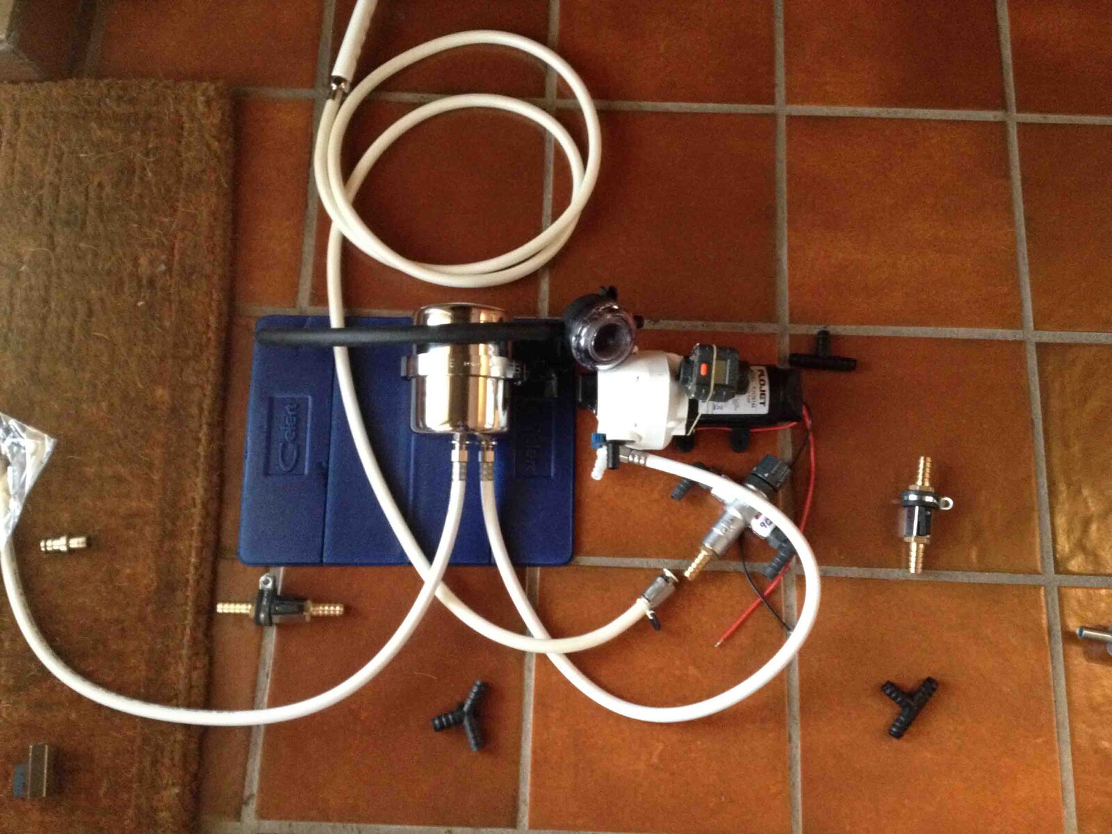
Received the remaining parts for the water filtration and shower system this week. Photo shows the approx. layout in the bin area adjacent to the offside wheel arch under the drawer side wings. Next step now that I have the major components laid out is to mount those components to the truck and do the final plumbing
IMG_1484 low res.jpg

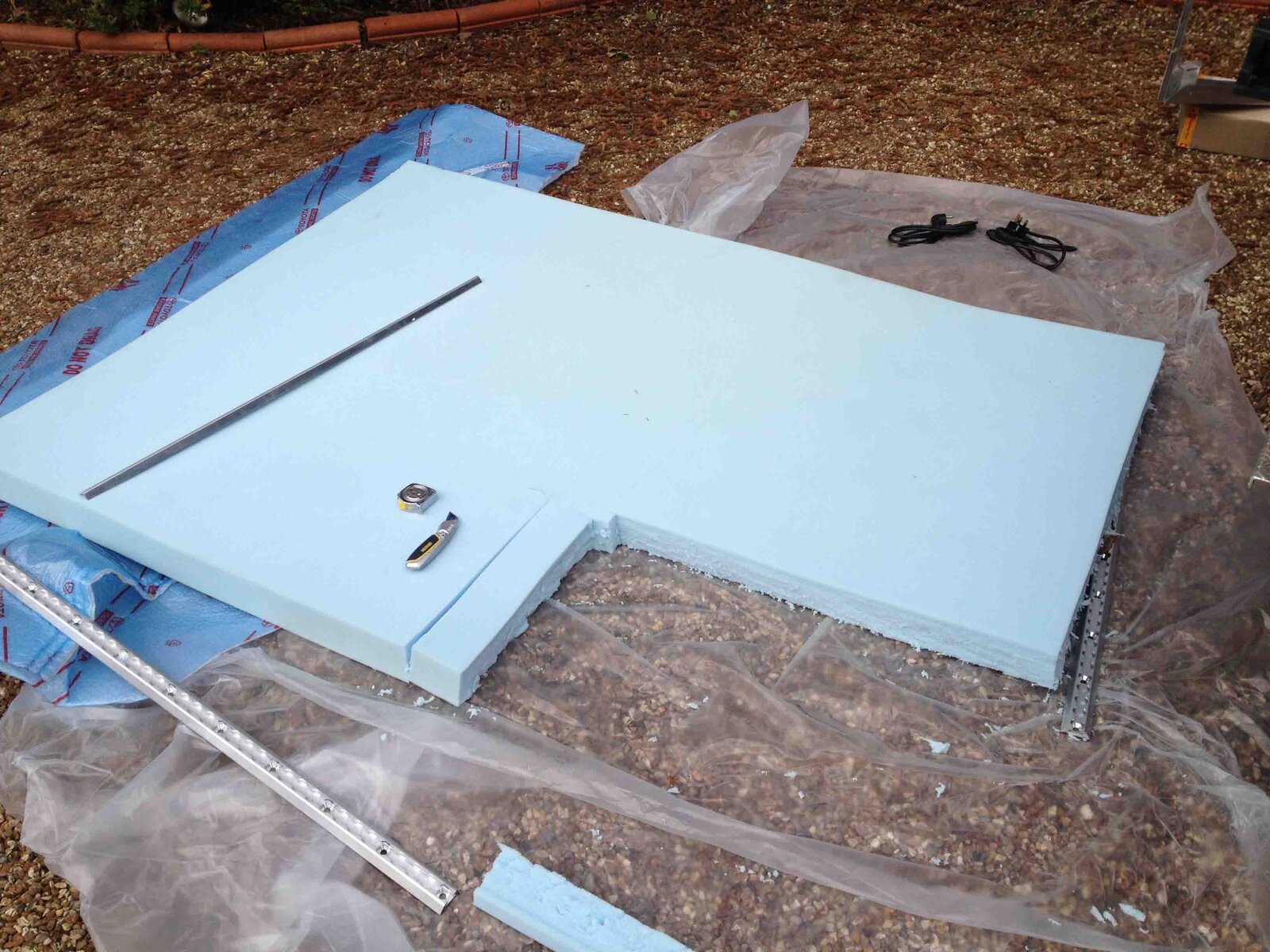
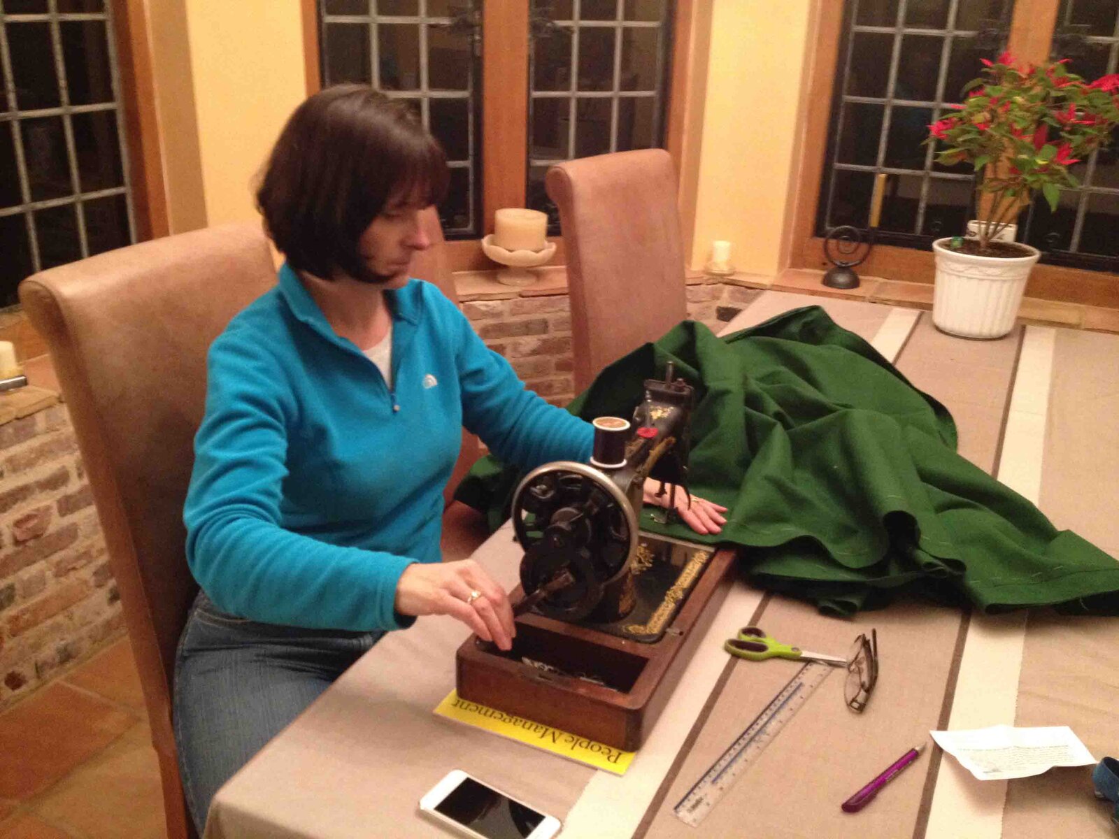
Also been busy sorting out the emergency sleeping arrangements. The sponge has been cut into an L shape to sit around the fridge and the resident seamstress has knocked up a cover to match the roof tent mattress material.
IMG_1479 low res.jpgIMG_1480 low res.jpg

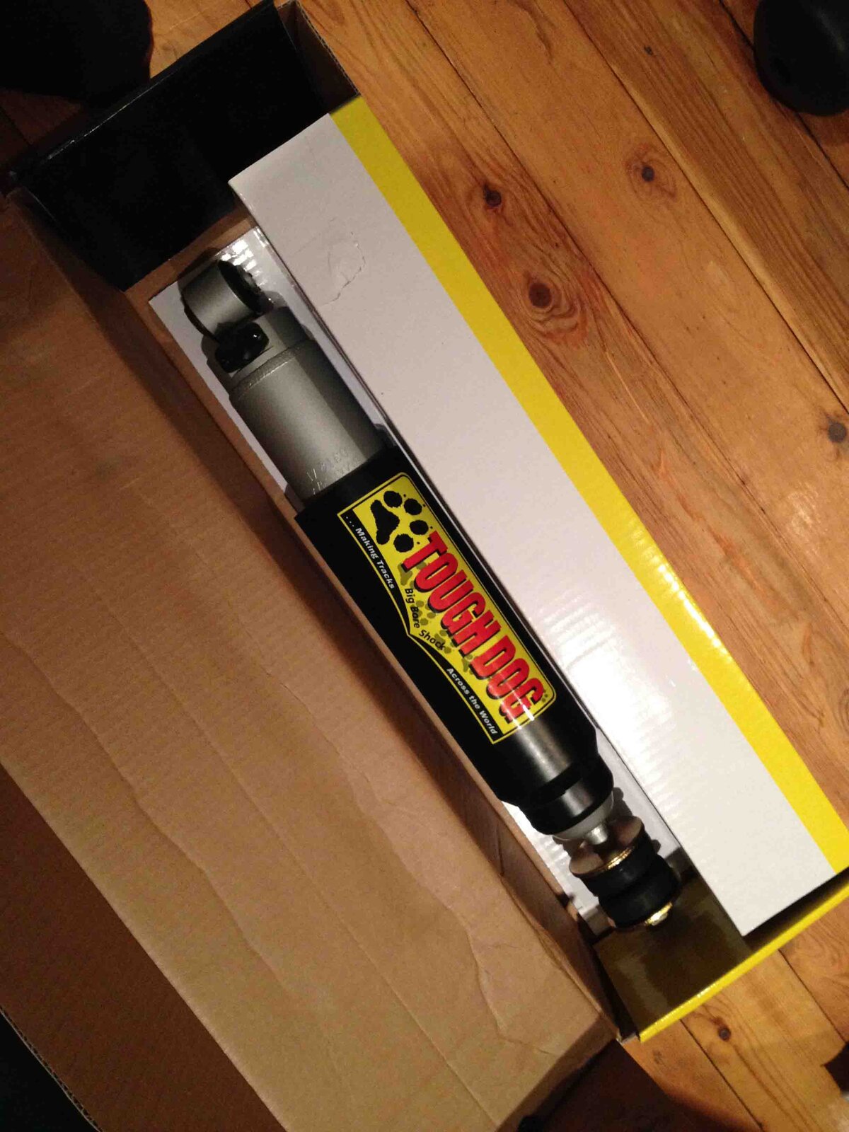
The Tough Dog rear shocks have arrived......they're mahoossive....and adjustable. The EFS springs are on their way.
IMG_1481 low res.jpg

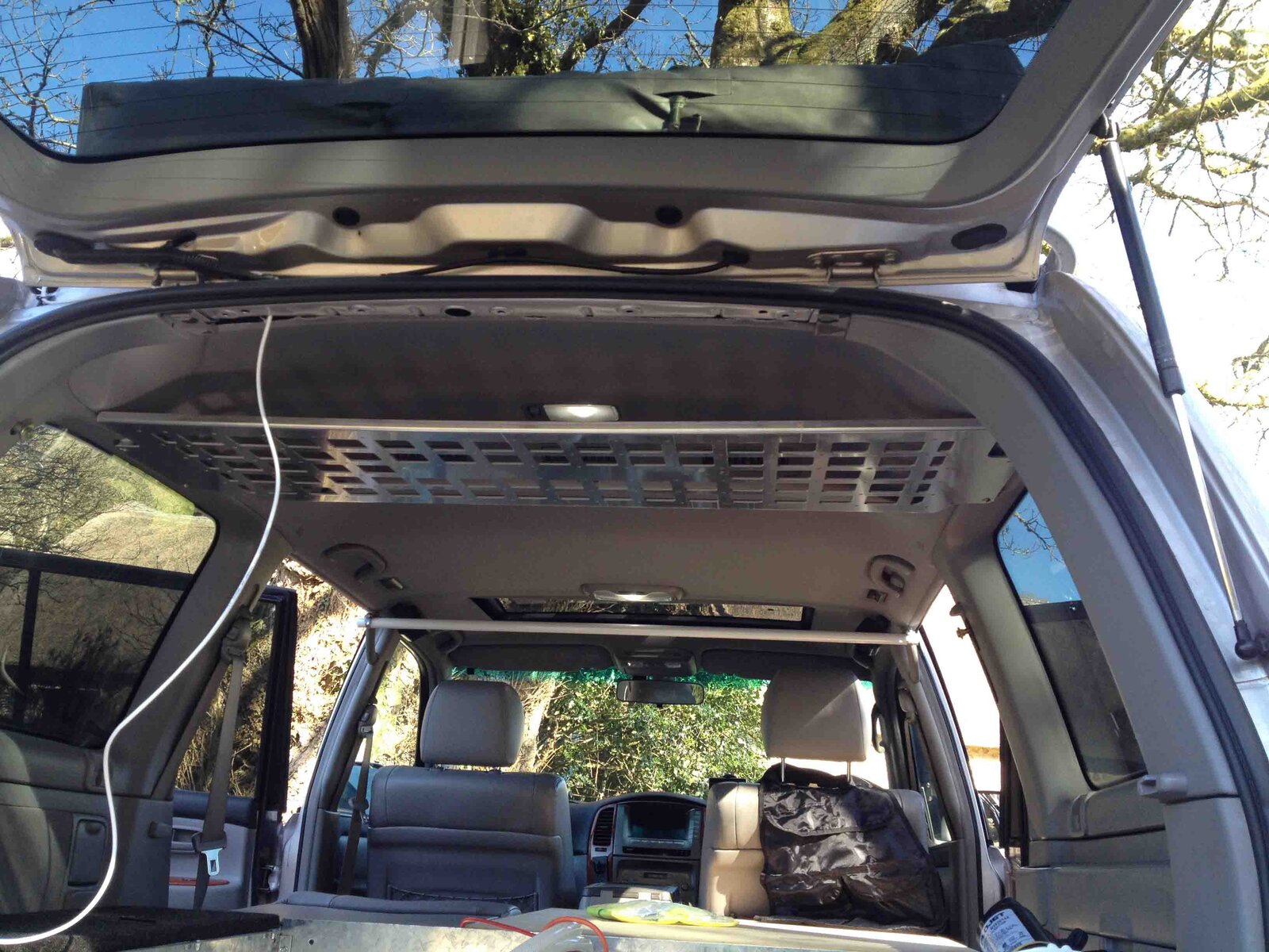
And have also been sorting out a few wrinkles with the custom high level shelf which I received from the fabricator the other day. Should get the final unit in the next two weeks.

IMG_1474 low res.jpg
 
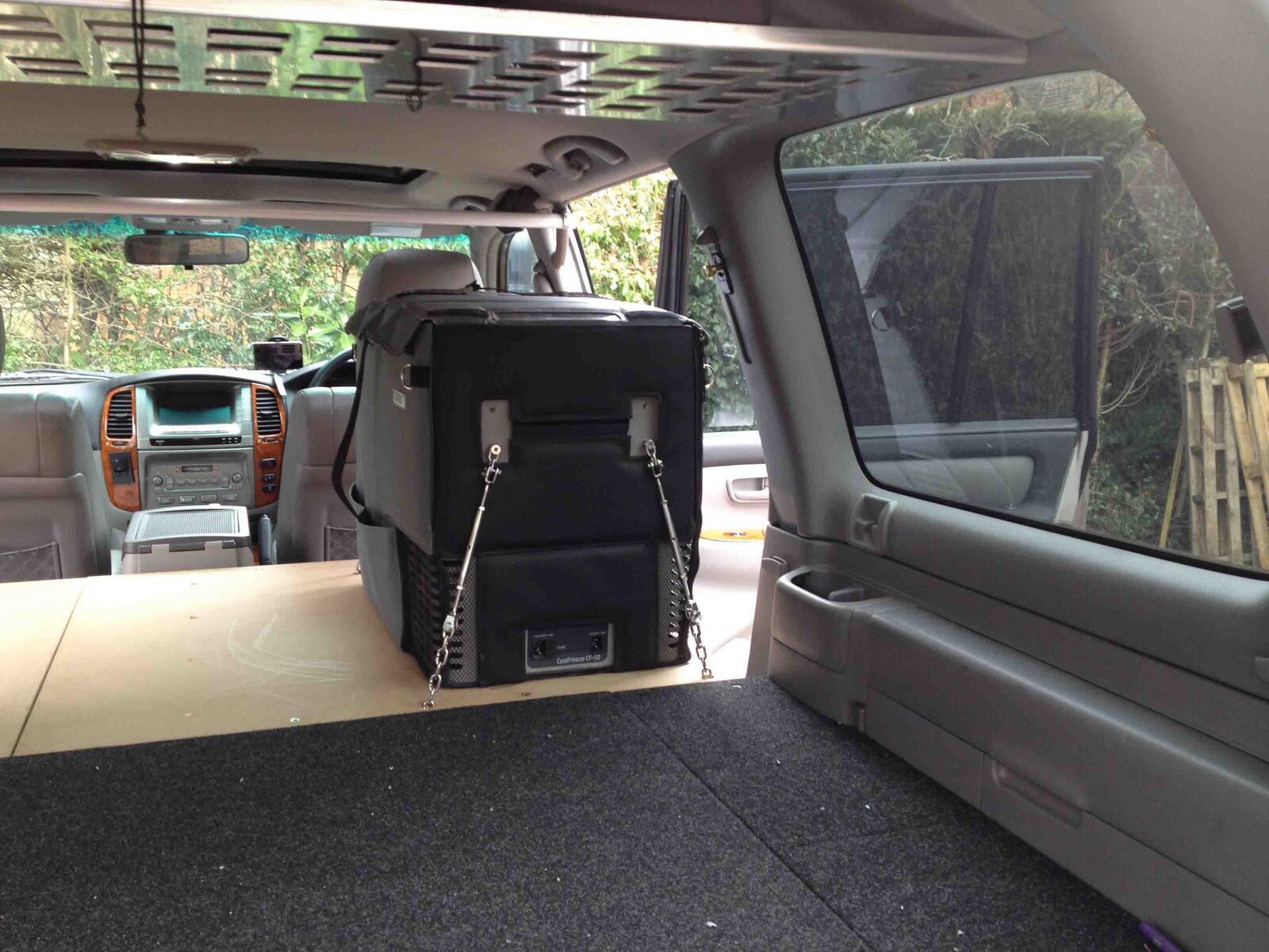
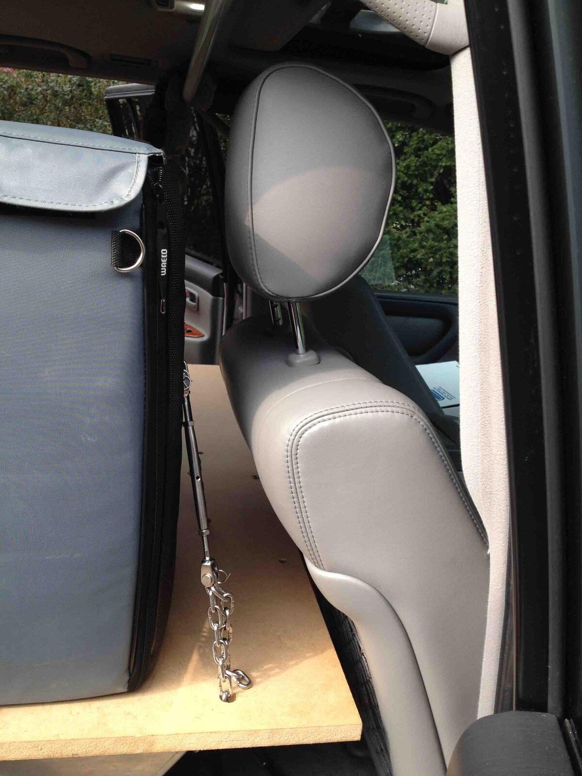
Fridge now installed. This time round I have discarded the fridge handles as this allows a more compact location of the fridge behind the drivers seat. I have used short sections of chain and turnbuckles to tighten up the chain as I can't use a ratchet strap. The tie downs are mounted off the handle mounting points. Also installed the 40% forward base to complete the flat load area/emergency sleeping area.

IMG_1486 low res.jpgIMG_1493 low res.jpg
 
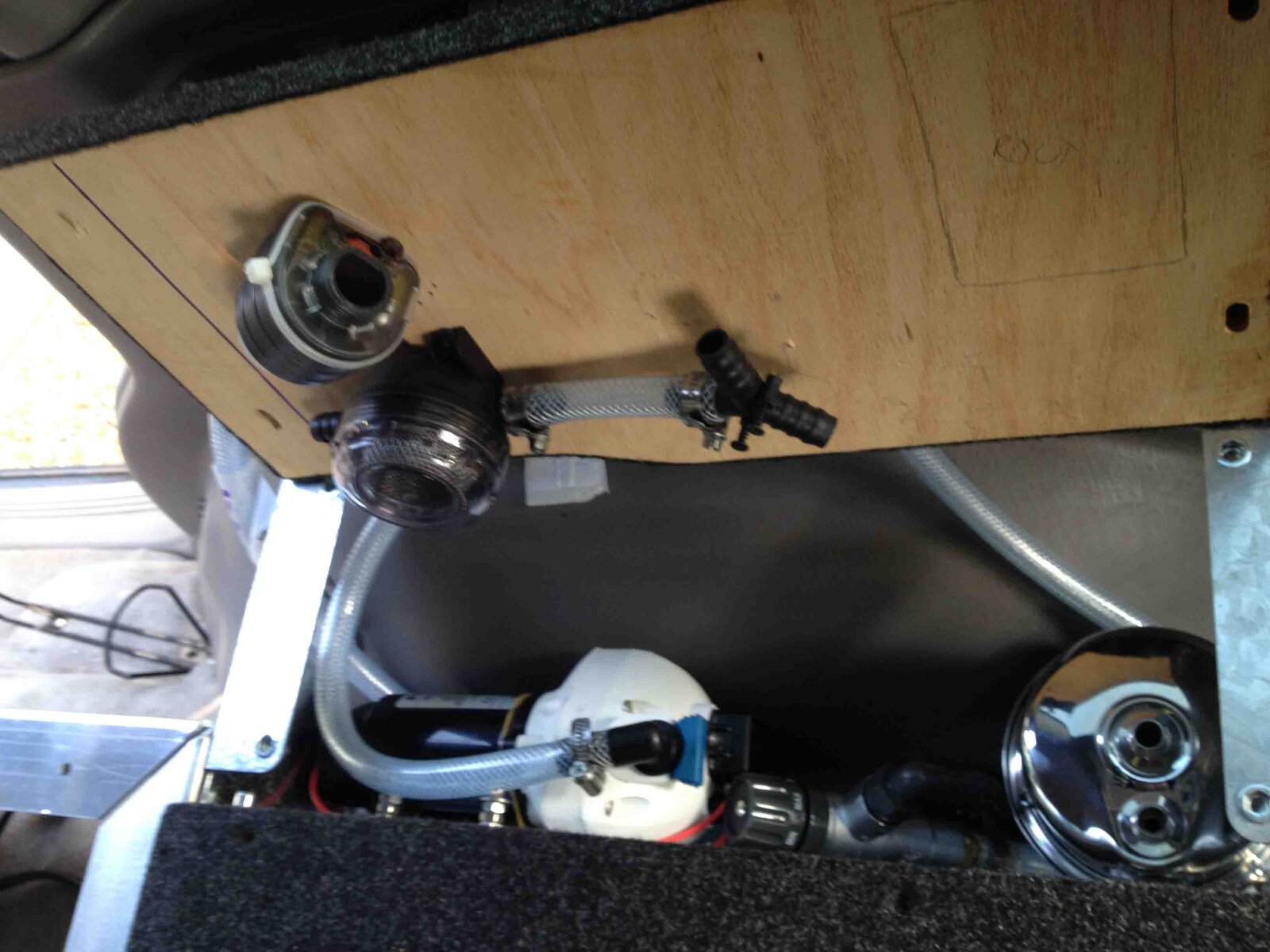
Sorted out more of the water system today. Still a day to finalise the connections before initial commissioning tests of the water purification system. This will test the pump, strainer, filter, pipework etc. I will also test the sand spear pickup. The hot water/shower system commissioning will have to wait until the Glind HE is installed. The picture shows all the major elements packed into the space over the rear wheel arch. Quite a tight fit but all items fit and are serviceable. The pump screen can be emptied easily and the Seagull filter can be changed out....although at 3800 litres capacity this is a rare event. The wooden lid holds the gauze pump screen and the metering unit. I will have to make a proper holder/strap for the metering unit. The unit LCD screen will be seen through a small opening in the wooden lid (eventually)

IMG_1495 low res.jpg
 
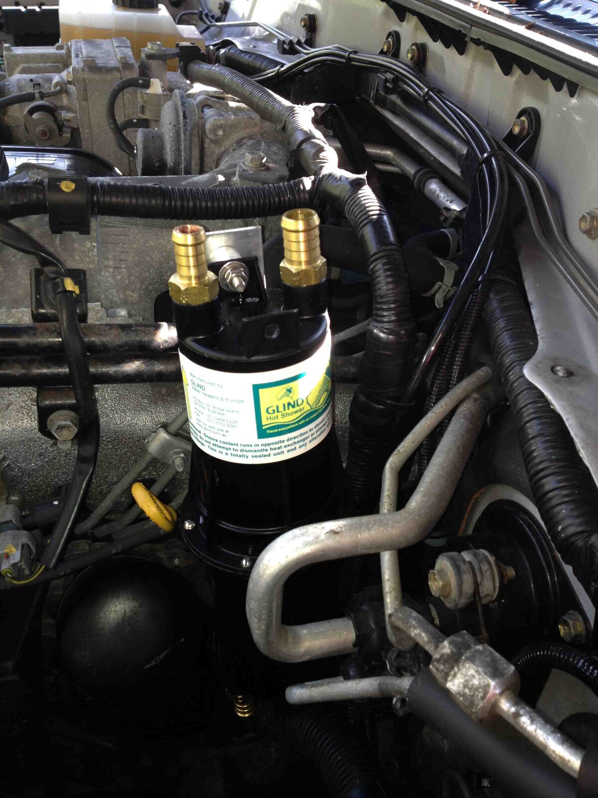
Spent some time today looking at the Glind Heat Exchanger location. The recommended position in the engine bay (by Glind) has quite a few complications - I think this must be a difference between a UK specced car and an Australian one. Glinds mounting pictures are similar but when put against a UK car there are just too many complications - cable looms in the way, additional pipework in the way, mounting points taken up by other things. Also Glind recommend that the HE is mounted off some bolts also used for the inlet manifold. Whilst these would be good fixings I don't fancy affecting these fixings if I can help it.

Approx location suggested by Glind

IMG_1506 low res.jpg

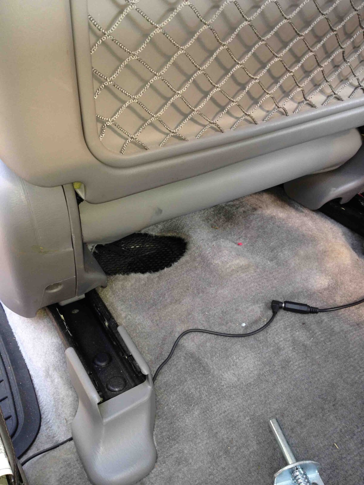
So where to put the HE? Following on from some earlier advice I decided to look into using the pipework for the second heater which is mounted under the passenger seat. This is largely superfluous now as there is no second or third row seating.

IMG_1507 low res.jpg


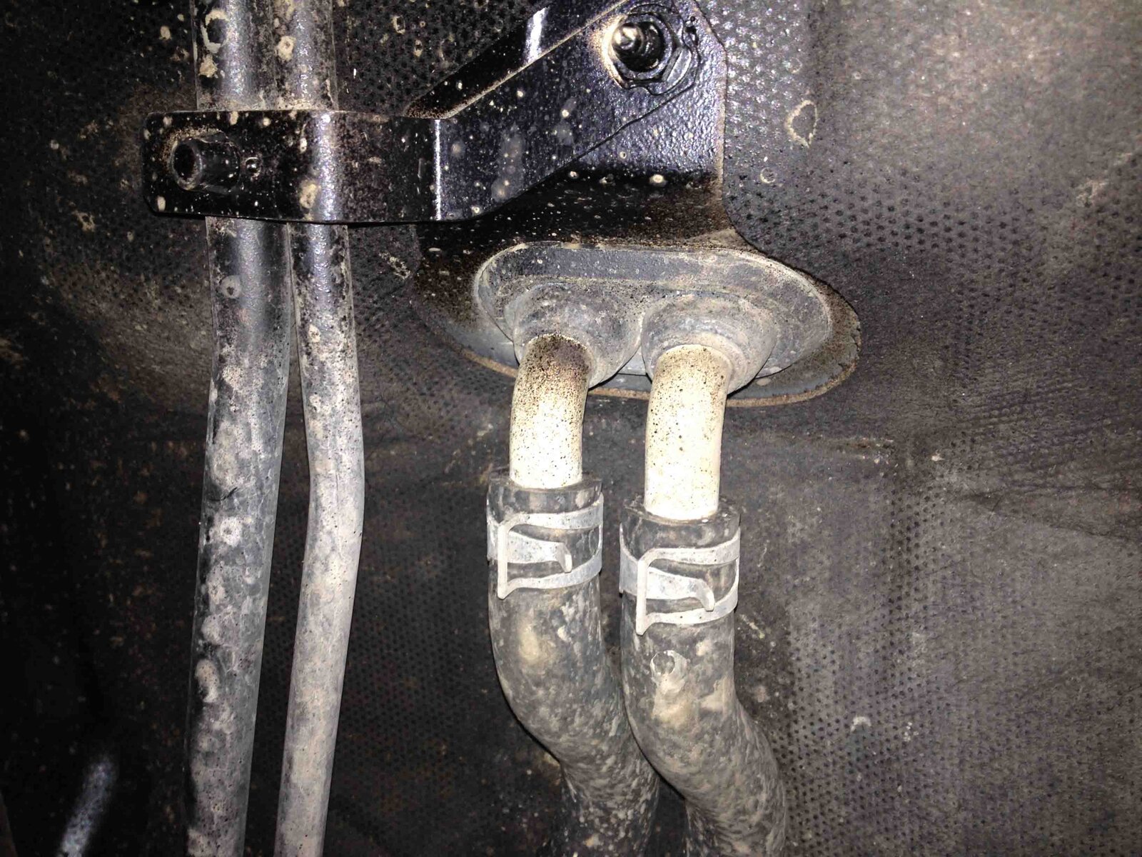
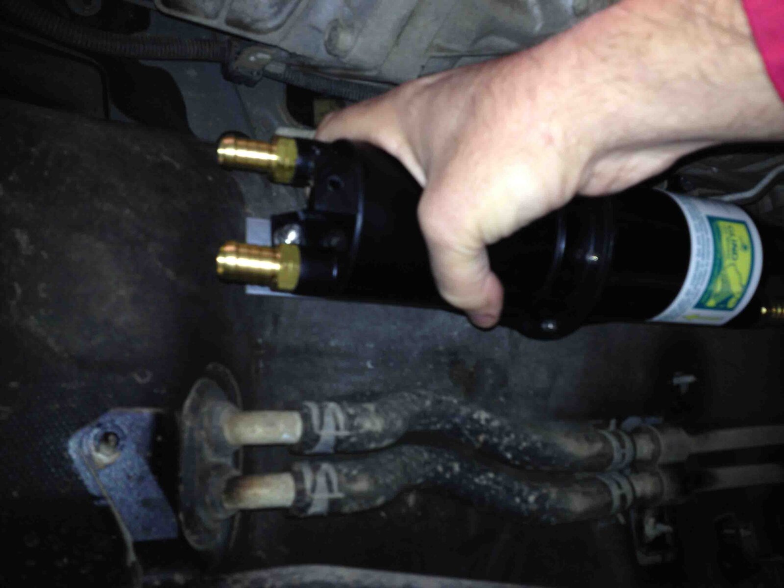
There is hot water pipework running under the truck and through the floor to the 2nd heater matrix: this would make plumbing in the glind heat exchanger either inside or outside the car a simple job.

IMG_1503 low res.jpg

If the HE is mounted outside the car then there is room for it under the passenger floor or on the cross member. Either would be good mounting points well out of harm's way and conveniently placed to pick up the existing hot water pipes.

HE sitting on the cross member (looking forward)

IMG_1502 low res.jpg


HE held in position under passenger floor

IMG_1505 low res.jpg

I will investigate further over the next few days but my preference now is to remove the rear heater unit - this will be a useful weight saving too - and to mount the Glind in its place, using the existing chassis holes to put the pipes through. This would also further simplify the shower/pump circuit and leave all the pipes in the car
 
Quick update on the WiFi range extender/active antenna/private hot-spot now being held in place by the RAM mount. This is shown in the upright position when we are stationary, when we're moving I can fold it down level with the rack if I wish


IMG_1498 low res.jpg
 
Here's my Glind mounting in the engine bay.
Mounted mine on the inlet manifold as its easier to get at the heater plumbing there. To the right you can see the water pump.
The HE water i/o connections are via garden hose click lock fittings underneath the front Roo bar.
Strongly suggest that you use at least three if not the four mounting tabs. If you use just two, eventually they'll snap with vibration. Bit of weight there with the water and copper.

glind1.jpg


glind2.jpg


You can see some of the heater hose routing here-
Out of the block into the H/E
glind4.jpg


HE return to cabin heater.
glind5_1.jpg
 
Last edited:
Back
Top