
Don't like the adverts? Click here to remove them
You are using an out of date browser. It may not display this or other websites correctly.
You should upgrade or use an alternative browser.
You should upgrade or use an alternative browser.
LJ70 Build Thread!
- Thread starter Ben
- Start date

Craigmorley
Well-Known Member
- Joined
- Apr 26, 2014
- Messages
- 341
- Country Flag

Having had that winch on my 70, I would say go for the 9.5 version. You'll appreciate the faster spooling speed. My 13000 was so so slow, caused a traffic jam when I winched up the farm track at Lincomb.
Thanks for that I'll keep that in mind just doing research at the mo
looking at various different ones so not sure yet

I'm no closer to deciding what suspension setup to go for but this is an interesting link about suspension links.
http://www.pirate4x4.com/tech/billavista/Links/
Maybe you could consider something on these lines Ben...

http://www.youtube.com/watch?v=KzEQYds1k3g&feature=player_detailpage
I'd do anything other than what's on that 80, I would look at Jeep set ups personally
mark test jeep flex with long arm kit at cowm: http://youtu.be/oBTJ8rNrN2E
mark test jeep flex with long arm kit at cowm: http://youtu.be/oBTJ8rNrN2E
- Joined
- Oct 13, 2010
- Messages
- 6,055
- Country Flag

I'd do anything other than what's on that 80, I would look at Jeep set ups personally
mark test jeep flex with long arm kit at cowm: http://youtu.be/oBTJ8rNrN2E
Video wont work for me.

Don't like the adverts? Click here to remove them
Video wont work for me.
Ah crap, was just a Jeep flexing, I would look at aftermarket set ups for Jeeps for ideas, they get really nice and even front to back flex
- Joined
- Oct 13, 2010
- Messages
- 6,055
- Country Flag
Cool. 
I was talking to the guys at work about me wanting more articulation and all sorts of ideas were thrown around and some one said I will need longer arms but.................................
Frankenzuke the Jimny I've built is running standard arms front and back in the standard configuration with a panhard rod and 2 arms (so 3 link) and the wheel base is the original length and that can lift any wheel onto a 44 gallon drum and all the other wheels stay on the ground! And thats a much shorter wheel base than LJ.
So it is possible to get huge flex out of a near standard setup.
I have been thinking about making all new links out of nice thick walled, seamless chromoly with rose joints on each end, but people have told me rose joints wouldn't be road legal over here.
Not a problem at the moment but certainly when I move states it could be as I might have to get various mods signed off by an engineer to say there safe, when I come to register the vehicle in my new state.
- Joined
- Oct 13, 2010
- Messages
- 6,055
- Country Flag
Update time...........................
A few work pics first.
I was given this battery box and told the customer will be back in an hour, can you build a mount for it so he can bolt it down securely in the back of his ute.


I made a tray.

And bent and drilled a top mount.


The customer wanted to be able to padlock it so it would be harder for people to steal it with his expensive Optima battery inside. So I welded on some thick washers.


Next I needed to make another batch of battery trays as the last batch I did have almost all been sold.
Laser cut and folded parts.


What they become.

In my jig.

First 2 welds.


A few hours later and I was running out of space.


With them all welded on one side they were ready to turn around to weld the other side.

Previously I had been marking each tray with a welding pencil and a combination square where the welds needed to start and finish, but I came up with the idea of a drop on plate with cuts showing where the welds should start and stop. This sped up production a lot!


The final welds were the 2 edges on the outside of the box/tray.


I loaded them onto a trolley ready for my final process.

I needed to punch the countersunk holes in for the mounting bolts.

Using this press tool I made on the lathe. No where near as beautiful and fancy as some of Chris's lather creations but it works ok.


I loaded them all into a stillage along with my rock sliders ready for electro plating.


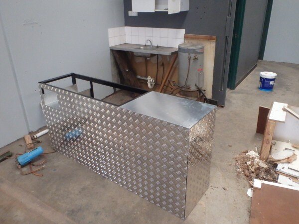
Another little project I had was to design and build a kitchen for a factory. The existing kitchen cupboard that was fitted was rotten and falling apart and rather than replace it with another chipboard unit it would be better to make a steel frame and cover it in alluminium with the sink at one end.


I took the frame for powder coating on Thursday and on Monday I should be picking it up and going and fitting it in the factory.
I took the rear bumper off LJ into work for the fixes and improvments I want to make to it.
Welded up the swing away wheel mount.


I wanted to weld up the damage from the swing out stop.


I carried in the bumper.

And a load of Lincomb sand fell out!

I'm not sure when I will find time to do the welding on LJ's rear bumper as things are pretty hectic at the moment but hopefully soon.
TAFE next................................
I didnt have time to machine more pipe at work on the lathe, so yesterday at Tafe I had to use the oxy pipe beveler.

Its basically a very slow turning lathe chuck with an oxy torch which you can adjust the angle of. So the pipe turns and the flame cuts.


After cleaning the pipe up with a grinder I could tack 2 pieces together.

I use a bent, de-fluxed welding rod as a spacer.

3 equally spaced 12mm long tacks.

Too much penetration on one.

These arrived this week. There called TIG fingers and they allow you to rest against the hot work piece and not burn your finger as easily/quickly.

Looks a bit like a Chinese finger trap.

I've also added a rest to my jig which should help a lot.


With the TIG finger and guide I'm now able to do this!

Did my root pass.


Next I did the much harder vertical weld. On the test I will have to weld 2 pieces of pipe together in the horizontal position and 2 in the vertical position.


The hardest bit is the bit underneath (overhead welding) as gravity keeps trying to push it out.

I will have to practice and improve upon this.


Penetration isnt good on the underside bit.

I did the hot passes.


And that was Tafe on Friday. Its frustratingly difficult but I will get the hang of it and I will pass the exams!
I acquired some rusty old strip lights the other day. They look shit but they were free and they work!

I only had one light in my garage which wasnt ideal and certainly not good enough for spray painting a car!


New lights up and working.


One of my pet hates is poor lighting in a workshop. It really annoys me when I'm trying to work and I cant see clearly enough. So I put one right above the work bench.


Now with all this new lighting I'd love to be able to say I can work on LJ every night but sadly that cant happen.
Monday, Wednesday and Thusday I'm out of the house at 6am for the gym then with work and TAFE I dont get home till 9.30pm! So that only leaves me Tuesday and Friday and those nights I feel exhausted and have to cook dinner, Tafe home work etc. But it wont be forever and is a means to an end!
Will be awesome once I've finished Tafe and have my welding certificates though!
Anyway...............................
Back to LJ.
I did some more filling and sanding.


I then fitted the new rear shoes after the guys at the brake shop told me the pins in the old shoes will hammer out, which they did.


Another job I've been meaning to do for a while on LJ is there has been excessive play in the steering column for a while and it can feel quite unsafe particularly at high speeds on the free way and when over taking as its harder to turn small amounts to keep the car going straight.

This short video shows the excessive play.
I knew none of the UJ's on the column that I could see had play in them and I'd established it wasnt play in the steering box or any of the components in the engine bay, so the column had to come out.

Column off.

These UJ's both felt good.


The UJ on the steering wheel end looked OK.


Much more visable with it turned over.

I could feel the movement wasnt in that UJ either and was in fact in the shaft between the 2 UJ's, so I would have to strip it down further.


Removed the 2 springs.

I needed to remove the 4 bolts next.


I could then remove the shaft.


So the movement was in this shaft some where.


I removed the end.

I needed to split the 2 sections of tube next, these are held together with a nylon bush containing bearings.


I needed to remove this section from inside the tube so I could see why the steering column piece was so loose.


Removed some more bits.

I used a piece of wood and a hammer to tap the nylon bush out that was holding the tube over the section I needed access to.


Basically the end of this square shaft is badly worn.


This short video shows and explains the issue:
Its pretty annoying that its the shaft that is worn and not one fo the much more easily replacable UJ's.
I will try and source a new shaft or good second hand one I think. If it wasnt for the tilt steering column I could just weld the 2 sections together.
Anyway.......................
So thats how I left LJ.


Oh almost forgot, these are the books I got from the US.

This is the one I was most interested in getting.

I'm hoping I can claim back the cost of them when I do my tax return which with all the tools I've been buying is going to be huge this year!
So I'm making some progress with LJ but theres lots still to do!
A few work pics first.
I was given this battery box and told the customer will be back in an hour, can you build a mount for it so he can bolt it down securely in the back of his ute.


I made a tray.

And bent and drilled a top mount.


The customer wanted to be able to padlock it so it would be harder for people to steal it with his expensive Optima battery inside. So I welded on some thick washers.


Next I needed to make another batch of battery trays as the last batch I did have almost all been sold.
Laser cut and folded parts.


What they become.

In my jig.

First 2 welds.


A few hours later and I was running out of space.


With them all welded on one side they were ready to turn around to weld the other side.

Previously I had been marking each tray with a welding pencil and a combination square where the welds needed to start and finish, but I came up with the idea of a drop on plate with cuts showing where the welds should start and stop. This sped up production a lot!


The final welds were the 2 edges on the outside of the box/tray.


I loaded them onto a trolley ready for my final process.

I needed to punch the countersunk holes in for the mounting bolts.

Using this press tool I made on the lathe. No where near as beautiful and fancy as some of Chris's lather creations but it works ok.


I loaded them all into a stillage along with my rock sliders ready for electro plating.


Another little project I had was to design and build a kitchen for a factory. The existing kitchen cupboard that was fitted was rotten and falling apart and rather than replace it with another chipboard unit it would be better to make a steel frame and cover it in alluminium with the sink at one end.


I took the frame for powder coating on Thursday and on Monday I should be picking it up and going and fitting it in the factory.
I took the rear bumper off LJ into work for the fixes and improvments I want to make to it.
Welded up the swing away wheel mount.


I wanted to weld up the damage from the swing out stop.


I carried in the bumper.

And a load of Lincomb sand fell out!

I'm not sure when I will find time to do the welding on LJ's rear bumper as things are pretty hectic at the moment but hopefully soon.
TAFE next................................
I didnt have time to machine more pipe at work on the lathe, so yesterday at Tafe I had to use the oxy pipe beveler.

Its basically a very slow turning lathe chuck with an oxy torch which you can adjust the angle of. So the pipe turns and the flame cuts.


After cleaning the pipe up with a grinder I could tack 2 pieces together.

I use a bent, de-fluxed welding rod as a spacer.

3 equally spaced 12mm long tacks.

Too much penetration on one.

These arrived this week. There called TIG fingers and they allow you to rest against the hot work piece and not burn your finger as easily/quickly.

Looks a bit like a Chinese finger trap.

I've also added a rest to my jig which should help a lot.


With the TIG finger and guide I'm now able to do this!

Did my root pass.


Next I did the much harder vertical weld. On the test I will have to weld 2 pieces of pipe together in the horizontal position and 2 in the vertical position.


The hardest bit is the bit underneath (overhead welding) as gravity keeps trying to push it out.

I will have to practice and improve upon this.


Penetration isnt good on the underside bit.

I did the hot passes.


And that was Tafe on Friday. Its frustratingly difficult but I will get the hang of it and I will pass the exams!
I acquired some rusty old strip lights the other day. They look shit but they were free and they work!

I only had one light in my garage which wasnt ideal and certainly not good enough for spray painting a car!


New lights up and working.


One of my pet hates is poor lighting in a workshop. It really annoys me when I'm trying to work and I cant see clearly enough. So I put one right above the work bench.


Now with all this new lighting I'd love to be able to say I can work on LJ every night but sadly that cant happen.
Monday, Wednesday and Thusday I'm out of the house at 6am for the gym then with work and TAFE I dont get home till 9.30pm! So that only leaves me Tuesday and Friday and those nights I feel exhausted and have to cook dinner, Tafe home work etc. But it wont be forever and is a means to an end!
Will be awesome once I've finished Tafe and have my welding certificates though!
Anyway...............................
Back to LJ.
I did some more filling and sanding.


I then fitted the new rear shoes after the guys at the brake shop told me the pins in the old shoes will hammer out, which they did.


Another job I've been meaning to do for a while on LJ is there has been excessive play in the steering column for a while and it can feel quite unsafe particularly at high speeds on the free way and when over taking as its harder to turn small amounts to keep the car going straight.

This short video shows the excessive play.
I knew none of the UJ's on the column that I could see had play in them and I'd established it wasnt play in the steering box or any of the components in the engine bay, so the column had to come out.

Column off.

These UJ's both felt good.


The UJ on the steering wheel end looked OK.


Much more visable with it turned over.

I could feel the movement wasnt in that UJ either and was in fact in the shaft between the 2 UJ's, so I would have to strip it down further.


Removed the 2 springs.

I needed to remove the 4 bolts next.


I could then remove the shaft.


So the movement was in this shaft some where.


I removed the end.

I needed to split the 2 sections of tube next, these are held together with a nylon bush containing bearings.


I needed to remove this section from inside the tube so I could see why the steering column piece was so loose.


Removed some more bits.

I used a piece of wood and a hammer to tap the nylon bush out that was holding the tube over the section I needed access to.


Basically the end of this square shaft is badly worn.


This short video shows and explains the issue:
Its pretty annoying that its the shaft that is worn and not one fo the much more easily replacable UJ's.
I will try and source a new shaft or good second hand one I think. If it wasnt for the tilt steering column I could just weld the 2 sections together.
Anyway.......................
So thats how I left LJ.


Oh almost forgot, these are the books I got from the US.

This is the one I was most interested in getting.

I'm hoping I can claim back the cost of them when I do my tax return which with all the tools I've been buying is going to be huge this year!
So I'm making some progress with LJ but theres lots still to do!
Paddler Ed
Well-Known Member
Cool.
I was talking to the guys at work about me wanting more articulation and all sorts of ideas were thrown around and some one said I will need longer arms but.................................
Frankenzuke the Jimny I've built is running standard arms front and back in the standard configuration with a panhard rod and 2 arms (so 3 link) and the wheel base is the original length and that can lift any wheel onto a 44 gallon drum and all the other wheels stay on the ground! And thats a much shorter wheel base than LJ.
So it is possible to get huge flex out of a near standard setup.
I have been thinking about making all new links out of nice thick walled, seamless chromoly with rose joints on each end, but people have told me rose joints wouldn't be road legal over here.
Not a problem at the moment but certainly when I move states it could be as I might have to get various mods signed off by an engineer to say there safe, when I come to register the vehicle in my new state.
I'd double check; I know in the Federal vehicle mods book they talk about Rose joints... here's some links for you... Technically you need to get it engineered what ever you do, even if it stays in VIC... and you're looking at coming to the most expensive state for Rego which also has annual roadworthy inspections.
On the subject of weather, this was about 100km south of up here today:

Other side of Nowendoc it was like this:

So we're sitting here in UK clothes... Buffalo jackets are back out, and I think I'm going to get my flanno lined jeans out if it gets much colder!
- Joined
- Oct 13, 2010
- Messages
- 6,055
- Country Flag
Technically! 
Might not register it in NSW might just keep it on Vic plates!
That is one thing I love about Vic! No yearly MOT style tests!

Just a shame its getting so bloody cold down here now!
In an un-insulated timber frame house with no heating on its freezing!
Wont be forever though! Another few years and I will be living in paradise!
Might not register it in NSW might just keep it on Vic plates!
That is one thing I love about Vic! No yearly MOT style tests!
Just a shame its getting so bloody cold down here now!
In an un-insulated timber frame house with no heating on its freezing!
Wont be forever though! Another few years and I will be living in paradise!
Attachments

Last edited:
- Joined
- Oct 13, 2010
- Messages
- 6,055
- Country Flag
Just caught up Ben! Got to admire your 'can do' attitude and your outlook on life. Keep up the good work!
Sent from my iPad using Tapatalk
Thanks mate.
Life is really good but I keep getting itchy feet! I just want to hit the road and spend a few years traveling!

Going to be a few more years before I think I can do that though!
Can you not cut the shaft and turn it round so the good bit is at the bottom?
Nice Idea Rich I like it!
The worn end has actually got pieces of nylon inset into it, so I would loose that but I don't think thats too critical.
I need to be careful whatever I do as its a collapsible steering column so is an important safety feature should I have an accident. If the steering column fails to collapse it will spear me through the chest!
I will have a look today and decide whether to turn it round and MIG it or take it to Tafe tomorrow and TIG it.
Duvs
Active Member
- Joined
- Aug 19, 2013
- Messages
- 69
then I thought it might just be better to cut all the suspension mounts off and start again from scratch!
hi Ben, i've found some new (to me) 70 series stuff today that you might like:
this 'mud thread seems to describe a pretty straightforward suspension mod. I'm looking forward to seeing what you decide to aim for.
i also came across a russian LC forum. I was viewing the pages in english using google chrome but a lot of the translation was poor. You can usually get the gist tho if you need to.
as you'd expect, they way they do things often seems a bit crazy. russian ingenuity etc.
but they're dedicated, and some of the info around the site is cool and not normally find-able.
among some of what it lead me to were the japan 70 club (had a little look around there too and found these examples, and this cool 70 series literature page.
back on the russian site, i scanned thru most of this thread. it threw up some cool pics and this Japanese supplier of suspension parts.
all the best
cruiser 3.0 70
New Member
- Joined
- Nov 9, 2012
- Messages
- 31
U could always build up the shaft with weld Ben then take it down with a flap disc for the perfect fit a lot easier fix
That 3 link is pretty much what I've got on my current cruiser and probably the easiest conversion for what your currently running, the new 70 is going to get an a frame set up, the same as what's on a land rover defender as I'm stretching the wheel base is will mean I don't have to relocate the panhard, just chop it off alltogether
- Joined
- Oct 13, 2010
- Messages
- 6,055
- Country Flag
hi Ben, i've found some new (to me) 70 series stuff today that you might like:
this 'mud thread seems to describe a pretty straightforward suspension mod. I'm looking forward to seeing what you decide to aim for.
i also came across a russian LC forum. I was viewing the pages in english using google chrome but a lot of the translation was poor. You can usually get the gist tho if you need to.
as you'd expect, they way they do things often seems a bit crazy. russian ingenuity etc.
but they're dedicated, and some of the info around the site is cool and not normally find-able.
among some of what it lead me to were the japan 70 club (had a little look around there too and found these examples, and this cool 70 series literature page.
back on the russian site, i scanned thru most of this thread. it threw up some cool pics and this Japanese supplier of suspension parts.
all the best

Thanks mate. I love that 3 link rear suspension setup on the LJ78 on the mud link! Think thats how I should do mine.
U could always build up the shaft with weld Ben then take it down with a flap disc for the perfect fit a lot easier fix
Yeah only trouble is I'd loose the nylon inserts and I think there important for it to slide in the event of an accident.
I've ordered one now, should be here in a few days. Decided with it being such an important safety thing that for the sake of £100 its not worth messing with.
That 3 link is pretty much what I've got on my current cruiser and probably the easiest conversion for what your currently running, the new 70 is going to get an a frame set up, the same as what's on a land rover defender as I'm stretching the wheel base is will mean I don't have to relocate the panhard, just chop it off all together
Yeah thats what I thought when I saw it.
Only real difference is he changed the bottom links as well.
Very interesting, when are you doing that?
- Joined
- Oct 13, 2010
- Messages
- 6,055
- Country Flag
Update time...............................
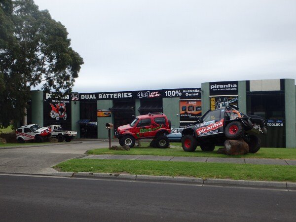
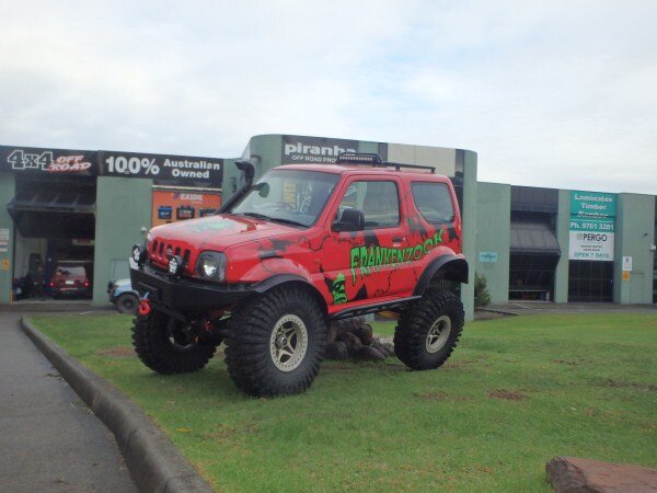
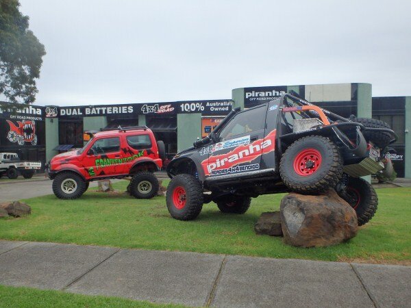
We had all the toys out on display this week.

Its the first time Frankenzuke has been out on display since being built.


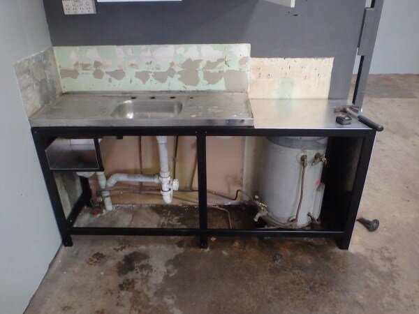
The kitchen I built last week got fitted.


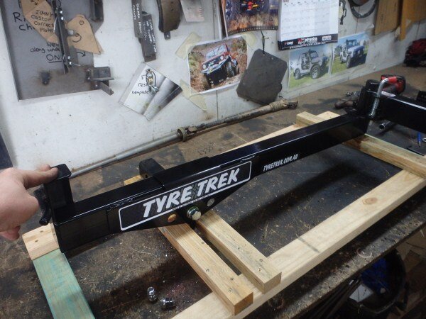
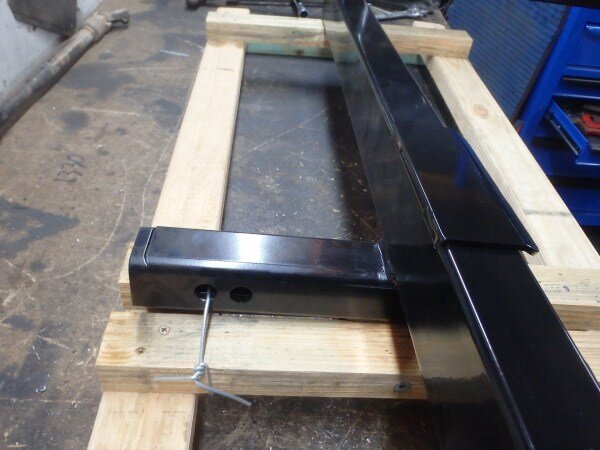
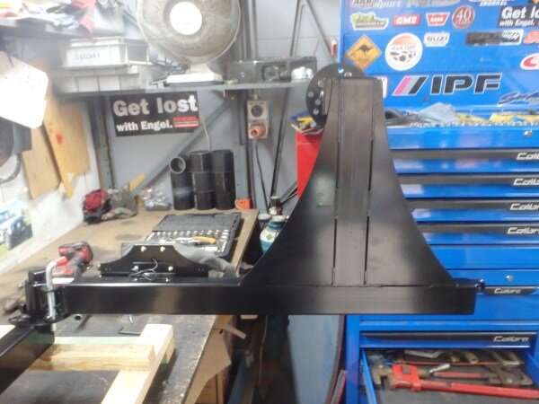
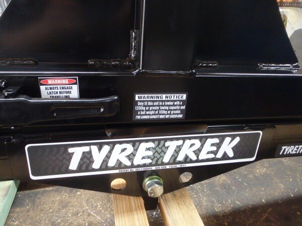
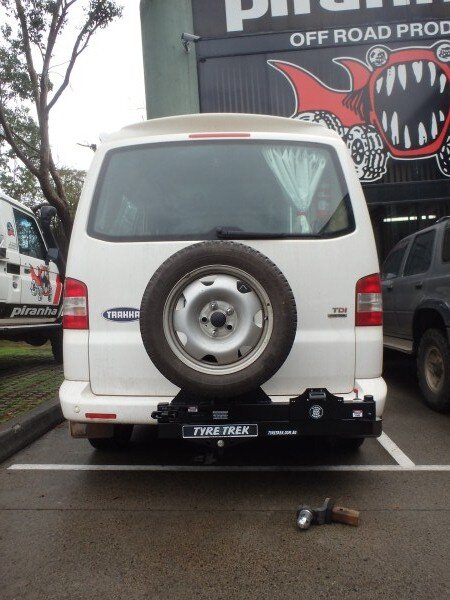
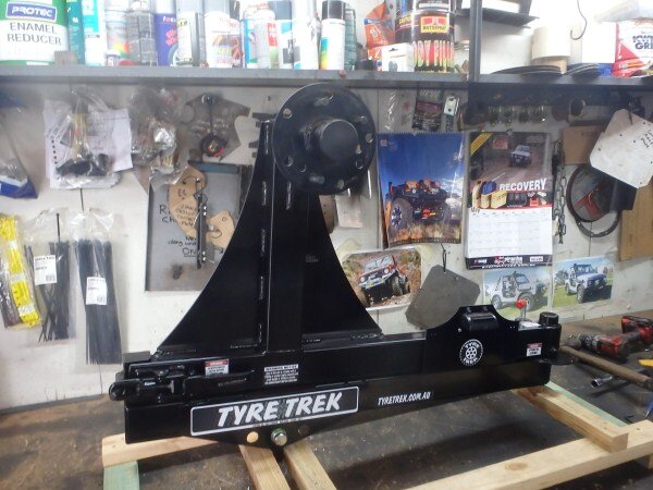
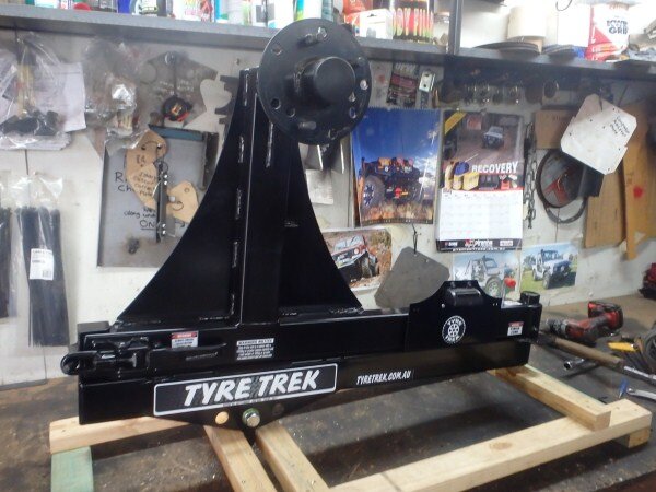
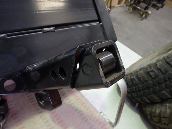
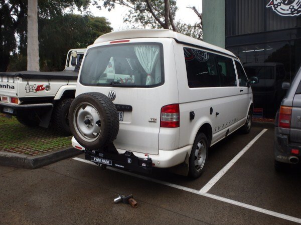
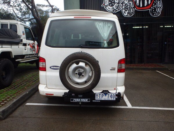
This is a swing away wheel carrier that mounts into a tow bar receiver hitch that I had to modify and fit.


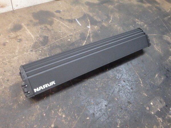
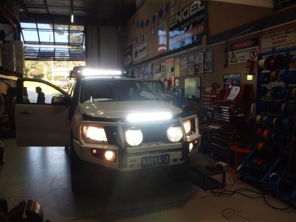
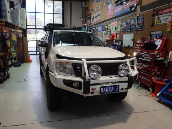
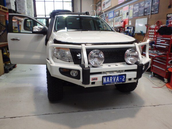
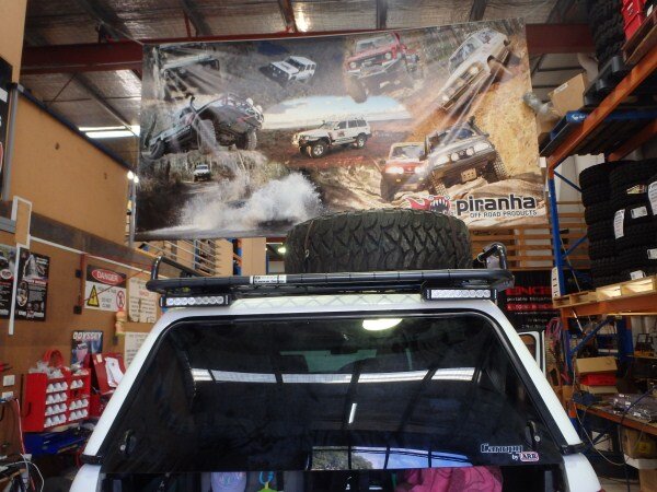
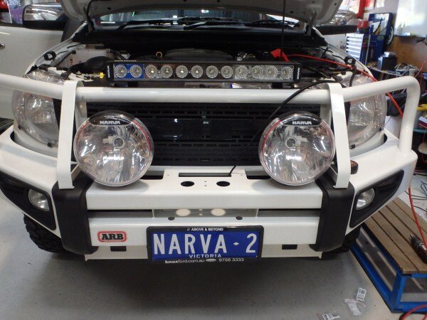
This is Narva's latest display/advertising vehicle.


We had to fit all their lights to it and do all the auto electrics. If you read any of the Australian 4wd magazines or watch any of the TV programs/DVD's then you will be seeing a lot more of this truck over the next few years.
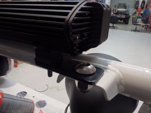
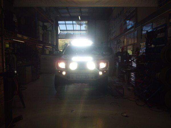
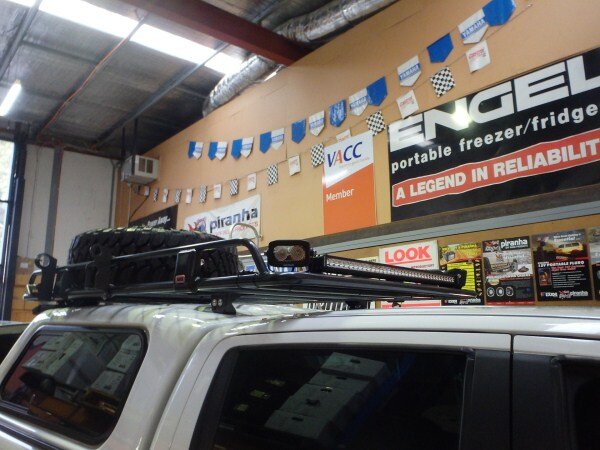
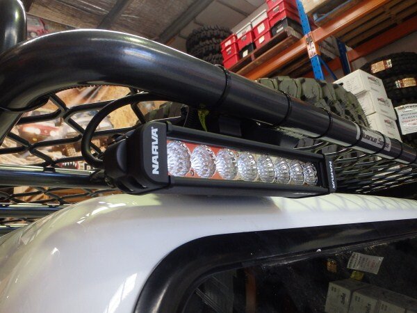
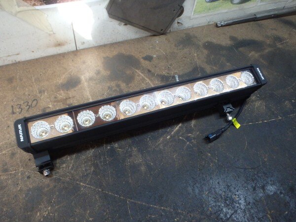
We fitted lots of lights!


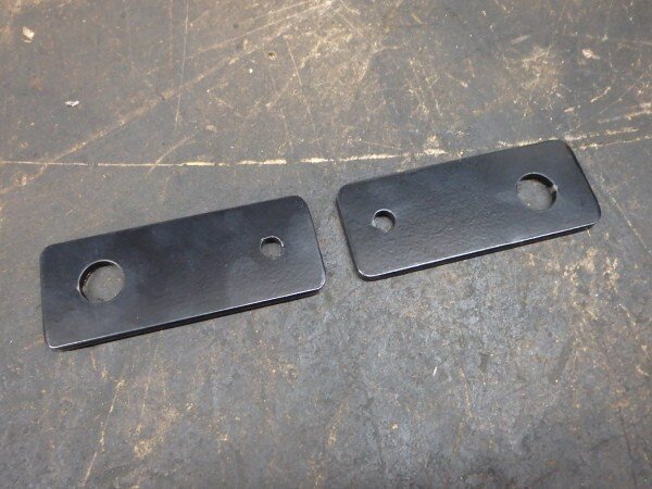
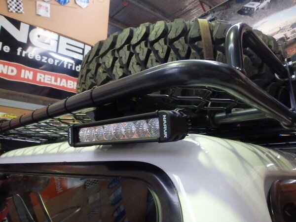
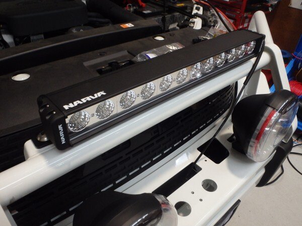
I had to make some brackets to fit this light bar onto the bullbar.


I got them powder coated.

And bolted it all together using stainless steel bolts.


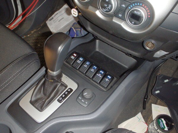
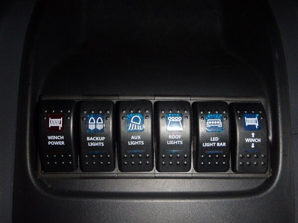
I also cut out a section of the center console for some switches.


Turning night into day!


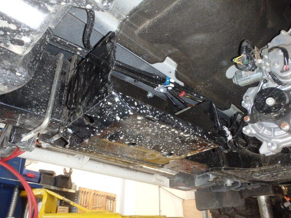
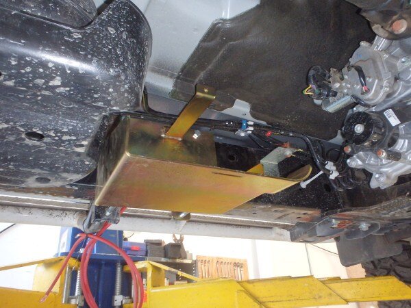
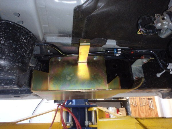
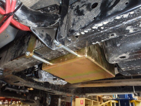
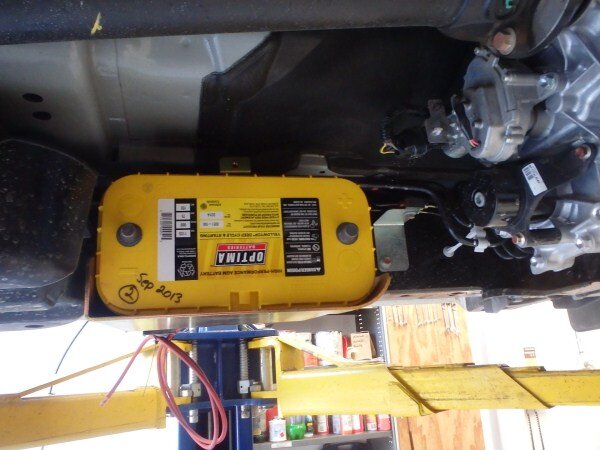
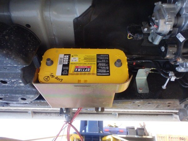
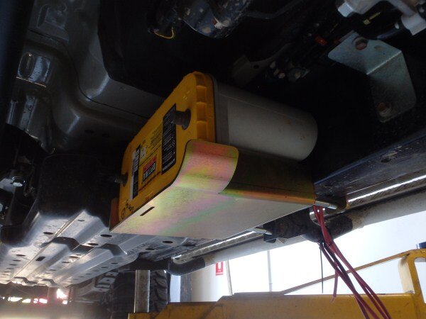
This is ARB's version of an underbody battery tray. Its made from thin, powder coated steel and only takes a 10" Optima.


We removed it and fitted one of ours as the customer had a 13" Optima they wanted to use.


I designed it to work with ARB side steps.


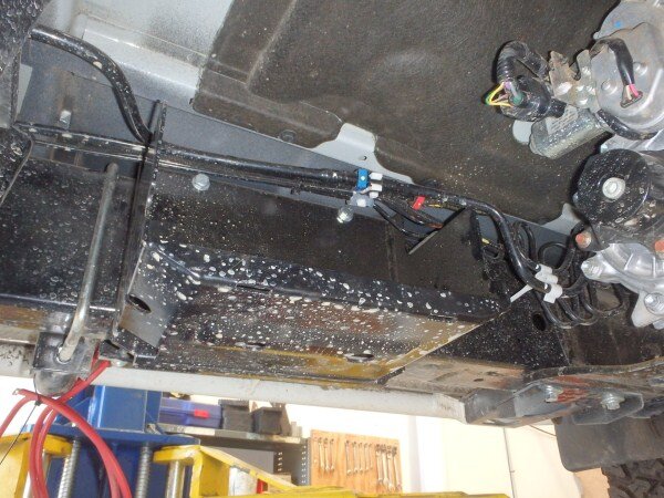
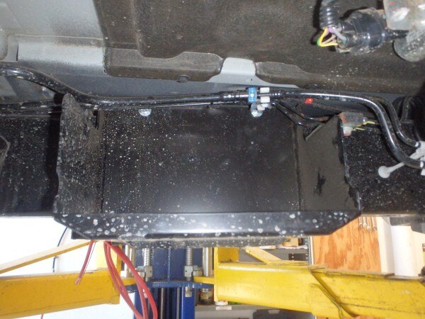
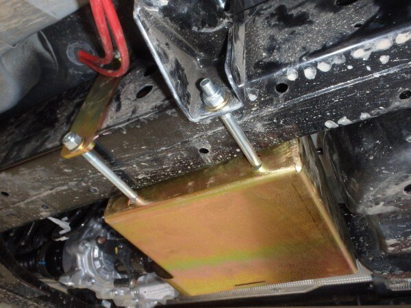
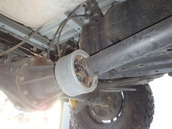
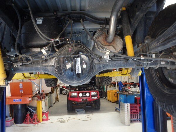
For the first time ever in Australia the mighty Hi-lux is no longer the biggest selling 4wd pick up! It has been beaten by the much cheaper Ford Ranger/Mazda BT50. But these vehicles have a few design faults that mean their really not suitable for off road use!
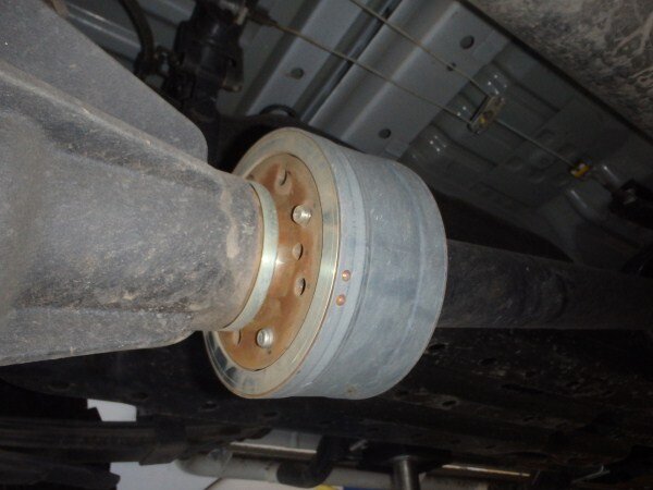
This balancer on the bottom of the rear prop shaft can easily get ripped off and damaged. This often means it flies around on the prop shaft for a while and hits the plastic fuel tank next to it. They have also been known to become jammed and the prop shaft gets twisted and snaps!


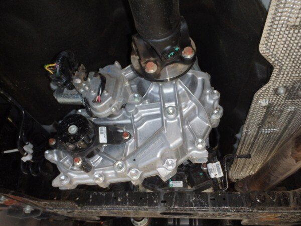
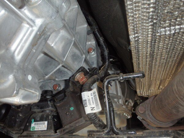
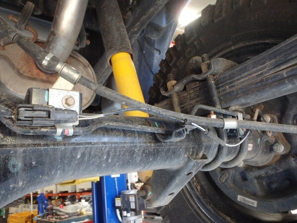
Another issue is all the wires and connectors around the gearbox and T box. If these get damaged by a stick etc. People find themselves stuck in low range.


Another issue is all the wires and connections on the rear axle, again easily damaged off road by stray sticks etc.


Its a real shame Ford have produced this vehicle! After all they know how to build good trucks, you only have to look at their hugely popular F truck's to see that!
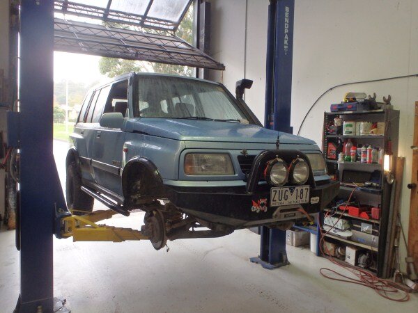
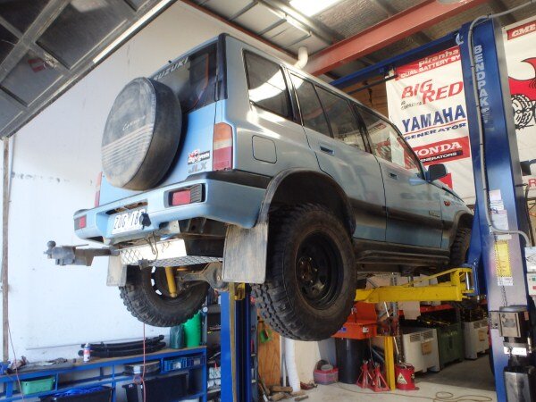
I had to do some work on a customers Vitara.

Got to test fit some alluminium fuel tank guards I've been making.


This is a Superior Engineering panhard rod off my ex-house mates 80 series. It snapped on him on a trip a few weeks ago.


I was meant to be on the trip too but pulled out at the last minute as I had only been living in my new house for a week and still had loads of sorting out to do.
Anyway....................
So he breaks the panhard rod while off road and did a bush repair using his winch to hold the axle in place for the weekend while off road.
He called the breakdown company when he got back on bitumen and they sent a recovery truck out. Only he got bored of waiting and decided to drive home slowly. After a while he decided it felt safe and increased the speed. At 110 kmh his wheel came off and he flipped the 80 writing it off!
Fortunately no one was hurt.

I finished Tafe early yesterday so went to work and did some work on LJs' rear bumper.

I wanted to try and reduce the weight a bit as being 5mm box its bloody heavy.
Decided to cut some out of the sides.


Marked an inch in.


Lots of Lincomb sand.

Other side.


I couldnt do this on the other side as the exhaust is there.

More sand.


I needed to fix the bent pin next.


I got it nice and hot.

And used a piece of wood and a hammer to hammer it straight.


I wanted to harden it by heating it up then quenching it in oil.
Used oil is better as it has more carbon in it.


Now in hindsight I should have done this outside as the second the red hot metal tocuched the oil the oil caught fire!
So I resorted to pouring the oil over the spindle and using the compressed air gun to keep blowing the flames out.


Another reason why next time I will do it outside is the huge plumes of agrid smoke that filled the workshop.

While the smoke cleared in the workshop I went outside and had a look at my bosses Kaymar bumper to see how they had done their swing out stop and gas strut.


Back on my rear bar.

I still had lots of sand falling out!

I wanted to cut my old stop off as it had been denting the box section on the swing out arm.


Bottom bearing on first.

Followed by the arm.

Top bearing, washer and nut.


I cut a piece of 10mm thick steel.

Cleaned some paint off.

And tacked it on.


Next I wanted to mount a gas strut.
One of these.


Decided to mount it under the arm like the Kaymar one to keep it out of the way.
Drilled a hole and found an M8 tap.


Worked out where on the arm the other mount needed to be.

Drilled and tapped.


I wanted to finish the stop next so that it opens to 90 degrees.


Cut a piece of 8mm.

And tacked it on.


I wanted to look at the catch next.

I needed to cut the old mount off as it would need to sit lower down.


I thought I may be able to just move the other part down one hole.


But then I wasnt sure if this would be in the way of the little rear door opening.
So thought I could mount it the other way.

So I decided really I need to bring it home and try it back on LJ to see how best to do it.

My compression tester also turned up this week so I can see what compression the cylinders of LJ's 1KZ-T are running at.

We had all the toys out on display this week.

Its the first time Frankenzuke has been out on display since being built.


The kitchen I built last week got fitted.


This is a swing away wheel carrier that mounts into a tow bar receiver hitch that I had to modify and fit.


This is Narva's latest display/advertising vehicle.


We had to fit all their lights to it and do all the auto electrics. If you read any of the Australian 4wd magazines or watch any of the TV programs/DVD's then you will be seeing a lot more of this truck over the next few years.
We fitted lots of lights!


I had to make some brackets to fit this light bar onto the bullbar.


I got them powder coated.

And bolted it all together using stainless steel bolts.


I also cut out a section of the center console for some switches.


Turning night into day!


This is ARB's version of an underbody battery tray. Its made from thin, powder coated steel and only takes a 10" Optima.


We removed it and fitted one of ours as the customer had a 13" Optima they wanted to use.


I designed it to work with ARB side steps.


For the first time ever in Australia the mighty Hi-lux is no longer the biggest selling 4wd pick up! It has been beaten by the much cheaper Ford Ranger/Mazda BT50. But these vehicles have a few design faults that mean their really not suitable for off road use!
This balancer on the bottom of the rear prop shaft can easily get ripped off and damaged. This often means it flies around on the prop shaft for a while and hits the plastic fuel tank next to it. They have also been known to become jammed and the prop shaft gets twisted and snaps!


Another issue is all the wires and connectors around the gearbox and T box. If these get damaged by a stick etc. People find themselves stuck in low range.


Another issue is all the wires and connections on the rear axle, again easily damaged off road by stray sticks etc.


Its a real shame Ford have produced this vehicle! After all they know how to build good trucks, you only have to look at their hugely popular F truck's to see that!
I had to do some work on a customers Vitara.

Got to test fit some alluminium fuel tank guards I've been making.


This is a Superior Engineering panhard rod off my ex-house mates 80 series. It snapped on him on a trip a few weeks ago.


I was meant to be on the trip too but pulled out at the last minute as I had only been living in my new house for a week and still had loads of sorting out to do.
Anyway....................
So he breaks the panhard rod while off road and did a bush repair using his winch to hold the axle in place for the weekend while off road.
He called the breakdown company when he got back on bitumen and they sent a recovery truck out. Only he got bored of waiting and decided to drive home slowly. After a while he decided it felt safe and increased the speed. At 110 kmh his wheel came off and he flipped the 80 writing it off!
Fortunately no one was hurt.

I finished Tafe early yesterday so went to work and did some work on LJs' rear bumper.

I wanted to try and reduce the weight a bit as being 5mm box its bloody heavy.
Decided to cut some out of the sides.


Marked an inch in.


Lots of Lincomb sand.

Other side.


I couldnt do this on the other side as the exhaust is there.

More sand.


I needed to fix the bent pin next.


I got it nice and hot.

And used a piece of wood and a hammer to hammer it straight.


I wanted to harden it by heating it up then quenching it in oil.
Used oil is better as it has more carbon in it.


Now in hindsight I should have done this outside as the second the red hot metal tocuched the oil the oil caught fire!
So I resorted to pouring the oil over the spindle and using the compressed air gun to keep blowing the flames out.


Another reason why next time I will do it outside is the huge plumes of agrid smoke that filled the workshop.

While the smoke cleared in the workshop I went outside and had a look at my bosses Kaymar bumper to see how they had done their swing out stop and gas strut.


Back on my rear bar.

I still had lots of sand falling out!

I wanted to cut my old stop off as it had been denting the box section on the swing out arm.


Bottom bearing on first.

Followed by the arm.

Top bearing, washer and nut.


I cut a piece of 10mm thick steel.

Cleaned some paint off.

And tacked it on.


Next I wanted to mount a gas strut.
One of these.


Decided to mount it under the arm like the Kaymar one to keep it out of the way.
Drilled a hole and found an M8 tap.


Worked out where on the arm the other mount needed to be.

Drilled and tapped.


I wanted to finish the stop next so that it opens to 90 degrees.


Cut a piece of 8mm.

And tacked it on.


I wanted to look at the catch next.

I needed to cut the old mount off as it would need to sit lower down.


I thought I may be able to just move the other part down one hole.


But then I wasnt sure if this would be in the way of the little rear door opening.
So thought I could mount it the other way.

So I decided really I need to bring it home and try it back on LJ to see how best to do it.

My compression tester also turned up this week so I can see what compression the cylinders of LJ's 1KZ-T are running at.

Attachments
-
 P5050011_zpsf7385343.jpg57.9 KB · Views: 56
 -
 P5050012_zps1da3aef4.jpg66.7 KB · Views: 69
 -
 P5050010_zps307d0e03.jpg52 KB · Views: 67
 -
 P5050013_zps32854fea.jpg60 KB · Views: 60
 -
 P5050014_zps0ea5fce6.jpg49.8 KB · Views: 69
 -
 P5050017_zps7447066a.jpg74.5 KB · Views: 66
 -
 P5050018_zpsd7c9748b.jpg74.5 KB · Views: 92
 -
 P5050019_zps87107c8b.jpg57.9 KB · Views: 68
 -
 P5050020_zps1378e638.jpg67.9 KB · Views: 61
 -
 P5050021_zps0d3cb606.jpg70.9 KB · Views: 65
 -
 P5050022_zpsddc45136.jpg61.1 KB · Views: 74
 -
 P5050023_zpsd9bbf81d.jpg47.3 KB · Views: 65
 -
 P5050024_zps7e9f6dab.jpg71.7 KB · Views: 63
 -
 P5050025_zps94c9503c.jpg92.6 KB · Views: 70
 -
 P5050026_zps06d46431.jpg70.6 KB · Views: 62
 -
 P5060032_zps61f18ef7.jpg73.4 KB · Views: 69
 -
 P5060030_zps98335658.jpg65.3 KB · Views: 51
 -
 P5060033_zps1d51e873.jpg73 KB · Views: 60
 -
 P5060040_zps4c2520be.jpg68.1 KB · Views: 58
 -
 P5070050_zps26e6c893.jpg83.7 KB · Views: 89
 -
 P5070051_zps5d455ffa.jpg70.6 KB · Views: 54
 -
 P5060028_zpsabff1818.jpg64.8 KB · Views: 61
 -
 P5060027_zpsc0282207.jpg67.1 KB · Views: 62
 -
 P5070041_zps75483cbf.jpg65.6 KB · Views: 53
 -
 P5070043_zps3fa1c052.jpg44.3 KB · Views: 54
 -
 P5070045_zps5529bee4.jpg73.3 KB · Views: 69
 -
 P5070044_zps42aaf689.jpg64.9 KB · Views: 76
 -
 P5070046_zpsa4be0d59.jpg71.7 KB · Views: 72
 -
 P5070048_zps3317f22e.jpg49.9 KB · Views: 61
 -
 P5070056_zpsdb8214c5.jpg56.6 KB · Views: 61
 -
 P5070057_zps89b0ffa0.jpg34.5 KB · Views: 55
 -
 P5080067_zps74947593.jpg88.2 KB · Views: 64
 -
 P5080068_zpsea8097b7.jpg71.1 KB · Views: 79
 -
 P5080069_zpsea5cc4c4.jpg95.1 KB · Views: 61
 -
 P5080075_zps9aff0d42.jpg78 KB · Views: 81
 -
 P5080076_zps4711a128.jpg62.6 KB · Views: 64
 -
 P5080077_zpsdc1f2cc9.jpg88.4 KB · Views: 64
 -
 P5080078_zpsb417157f.jpg76.8 KB · Views: 55
 -
 P5080079_zps154fdf7c.jpg62.2 KB · Views: 53
 -
 P5080080_zpsc9efdbd5.jpg59.7 KB · Views: 67
 -
 P5080081_zpsb68db41e.jpg51.1 KB · Views: 63
 -
 P5080070_zps3d24e20f.jpg59 KB · Views: 99
 -
 P5080071_zpsd9533793.jpg46.8 KB · Views: 59
 -
 P5080072_zps8e23ead4.jpg64 KB · Views: 54
 -
 P5080073_zps66ef8e67.jpg75.2 KB · Views: 67
 -
 P5080082_zps5c3598e8.jpg76.8 KB · Views: 65
 -
 P5080083_zpsb8f278a6.jpg80.9 KB · Views: 103
 -
 P5050015_zps0610c32c.jpg67 KB · Views: 60
 -
 P5080064_zps87f07842.jpg79.9 KB · Views: 59
 -
 P5050011_zpsf7385343.jpg57.9 KB · Views: 59
 -
 P5050012_zps1da3aef4.jpg66.7 KB · Views: 60
 -
 P5050010_zps307d0e03.jpg52 KB · Views: 64
 -
 P5050013_zps32854fea.jpg60 KB · Views: 62
 -
 P5050014_zps0ea5fce6.jpg49.8 KB · Views: 58
 -
 P5050017_zps7447066a.jpg74.5 KB · Views: 56
 -
 P5050018_zpsd7c9748b.jpg74.5 KB · Views: 72
 -
 P5050019_zps87107c8b.jpg57.9 KB · Views: 56
 -
 P5050020_zps1378e638.jpg67.9 KB · Views: 67
 -
 P5050021_zps0d3cb606.jpg70.9 KB · Views: 58
 -
 P5050022_zpsddc45136.jpg61.1 KB · Views: 70
 -
 P5050023_zpsd9bbf81d.jpg47.3 KB · Views: 64
 -
 P5050024_zps7e9f6dab.jpg71.7 KB · Views: 65
 -
 P5050025_zps94c9503c.jpg92.6 KB · Views: 72
 -
 P5050026_zps06d46431.jpg70.6 KB · Views: 55
 -
 P5060032_zps61f18ef7.jpg73.4 KB · Views: 64
 -
 P5060030_zps98335658.jpg65.3 KB · Views: 62
 -
 P5060033_zps1d51e873.jpg73 KB · Views: 64
 -
 P5060040_zps4c2520be.jpg68.1 KB · Views: 57
 -
 P5070050_zps26e6c893.jpg83.7 KB · Views: 58
 -
 P5070051_zps5d455ffa.jpg70.6 KB · Views: 55
 -
 P5060028_zpsabff1818.jpg64.8 KB · Views: 51
 -
 P5060027_zpsc0282207.jpg67.1 KB · Views: 53
 -
 P5070041_zps75483cbf.jpg65.6 KB · Views: 65
 -
 P5070043_zps3fa1c052.jpg44.3 KB · Views: 53
 -
 P5070044_zps42aaf689.jpg64.9 KB · Views: 63
 -
 P5070045_zps5529bee4.jpg73.3 KB · Views: 49
Paddler Ed
Well-Known Member
I wanted to harden it by heating it up then quenching it in oil.
Used oil is better as it has more carbon in it.
Now in hindsight I should have done this outside as the second the red hot metal tocuched the oil the oil caught fire!
So I resorted to pouring the oil over the spindle and using the compressed air gun to keep blowing the flames out.
Another reason why next time I will do it outside is the huge plumes of agrid smoke that filled the workshop.

That's brilliant on the fire/smoke... had me in creases!