Don't like the adverts? Click here to remove them
You are using an out of date browser. It may not display this or other websites correctly.
You should upgrade or use an alternative browser.
You should upgrade or use an alternative browser.
my grey 80
- Thread starter Jon Wildsmith
- Start date


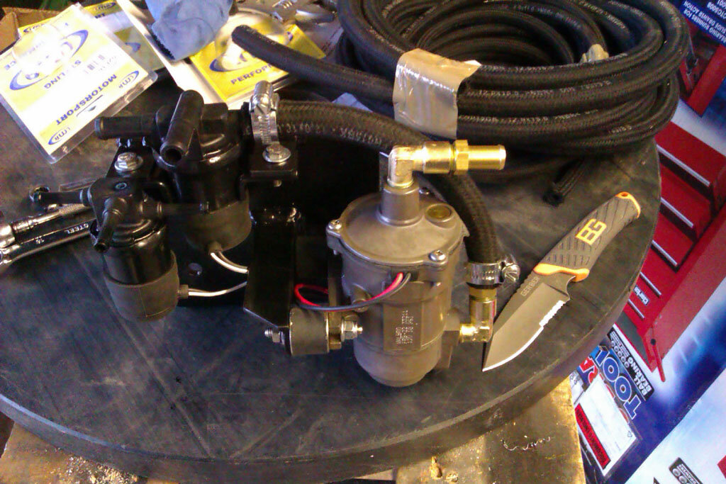
Bobbins and NPT fittings for the pump are parts I'm waiting for. For the pump fittings I'm using straight NPT tails with 90 degree NPT male to NPT female elbows so combined they give me a 90 degree NPT tail. The pump will suck through the valve from whichever tank is active which by default is the main but if the valves are powered up they switch to the aux. Using the self priming pusher pump means if I run one of the tanks dry I won't have to manually prime the systemChris said:Hi Jon, I can't quite see the set up there, but have you mounted the actual pump on bobbins? They tick pretty loudly and can transmit that though the chassis. Don't know if it's a Walbro like mine, but when I struggled to get NPT fittings, I found that polypropylene BSPT ones tightened in quite nicely.
Is that just a transfer pump between the tanks or a pusher to the main IP as well?
Thanks, I'm pretty pleased with how they've turned out. Not much danger of me needing to mount a bikeNeil Stone said:Love the draw system Jon.

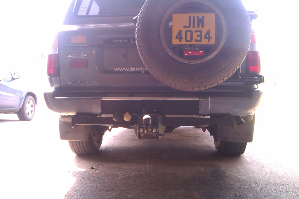
I'd not stick the number plate on the spare personally, as I mite use the spare wheel for hanging a mountain bike rack from.
The tank is a Long Ranger from a friend. If this one hadn't been available I was thinking of either adapting an OEM tank or just making one. An 80 has a huge space under the back if you get the spare out from under and is ideal for an aux tank.AndyCook said:Aux fuel tank mod looks interesting. are you using an OEM tank or an aftermarket one?
warrenpfo
Well-Known Member
- Joined
- Jul 21, 2010
- Messages
- 2,895
Jon Wildsmith said:The tank is a Long Ranger from a friend.
I wish my friends had longrangers they did not need.
Yes, the price was even better, I think he must have stopped taking his medication or something when I asked my new best friendwarrenpfo said:I wish my friends had longrangers they did not need.
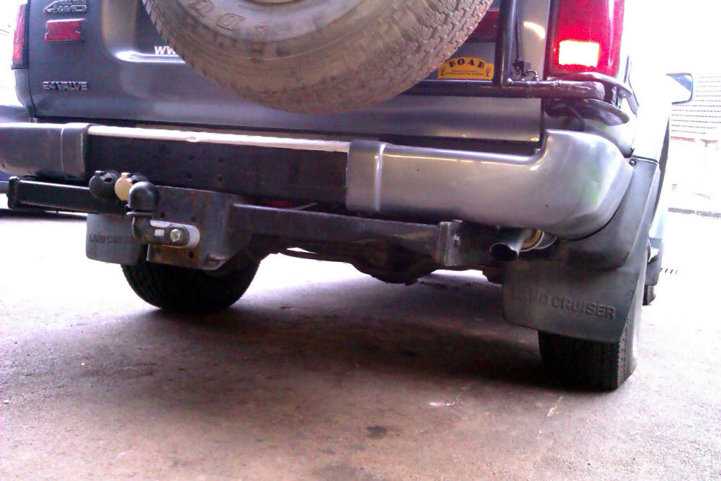
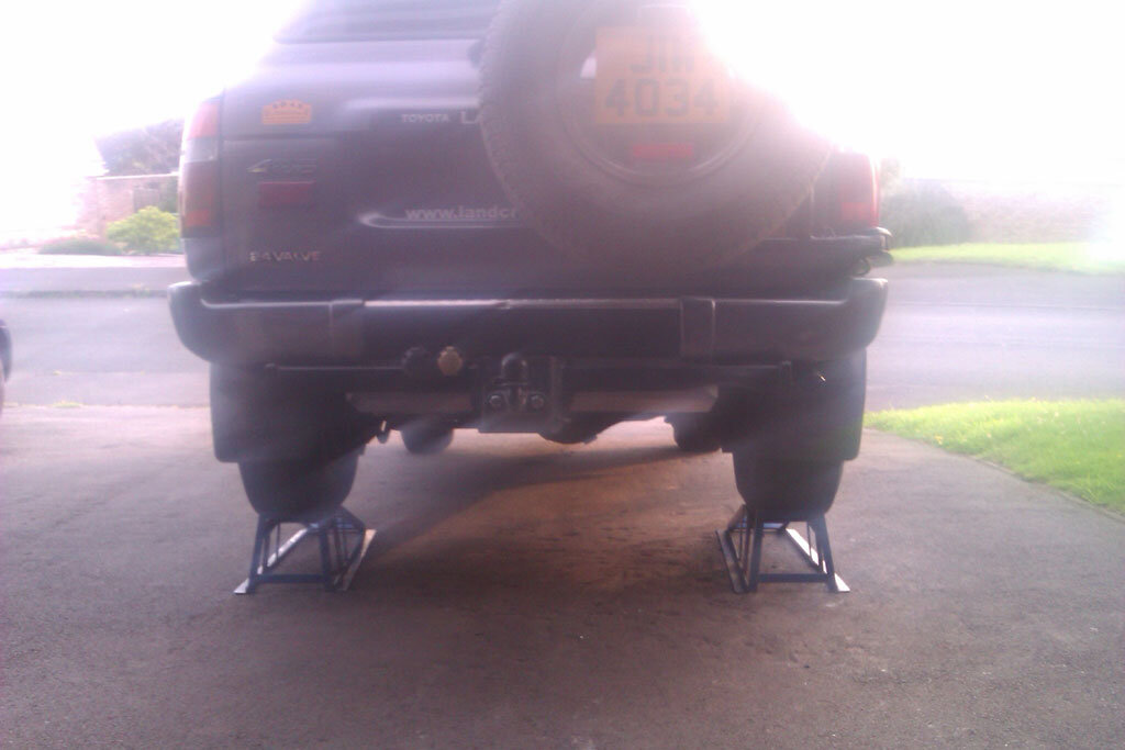
Slowly creeping towards getting the aux tank installed and another job ticked off the list now is swapping the exhaust rear pipe for the older style. Mine had the pipe with the bigger silencer that sits inside the chassis rails which is no good for fitting the aux tank so I've swapped it for the old style. I did consider just chopping the existing pipe and knocking up a side exit but the existing pipe was quite rusty so it seemed a false economy to be bodging that. I got a cheap pipe from Milner that will get the job done and maybe at a later date I'll sort out a stainless system with side exit. Not a lot to see really but here's a picture anyway. Notice the 'dent' in the tow bar where the original pipe finished.
[attachment=1:3sjlqhud]IMAG1086.jpg[/attachment:3sjlqhud]
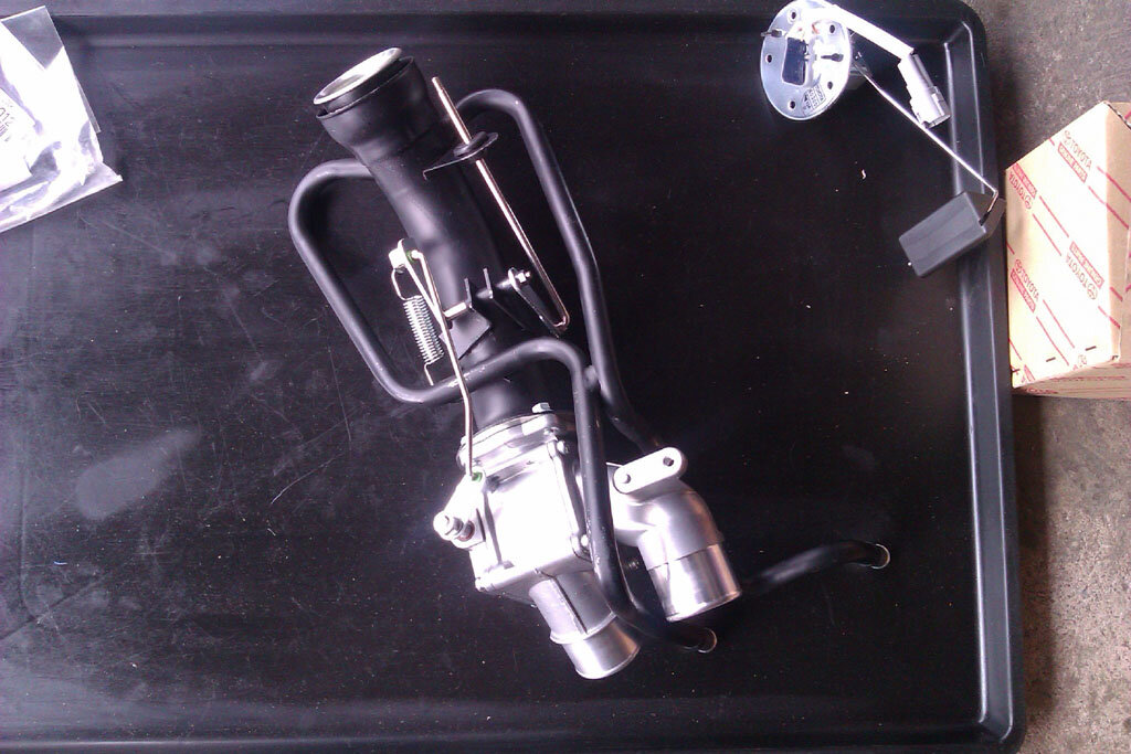
Had some deliveries today that included bobbins and pipe fittings for the pump and some hose. Chris might recognise the work surface")
[attachment=0:3sjlqhud]IMAG1088.jpg[/attachment:3sjlqhud]
[attachment=1:3sjlqhud]IMAG1086.jpg[/attachment:3sjlqhud]
Had some deliveries today that included bobbins and pipe fittings for the pump and some hose. Chris might recognise the work surface
[attachment=0:3sjlqhud]IMAG1088.jpg[/attachment:3sjlqhud]
Attachments
Don't like the adverts? Click here to remove them

See! I said it was multi functional. I have been using some to make spacers for my deck inside where I have plumbed in my water tank. It machines up very nicely.
Nice goodies there Jon. Lovely bit of hose. Tidy port fittings too.
Chris
Nice goodies there Jon. Lovely bit of hose. Tidy port fittings too.
Chris
Weaker than un-dented but it's how they are made so strong enough for the job I'm sureAndyCook said:must have weakened the towbar a fair bit!?
nice new shiney stuff and hoses
and a new tool chest too?
I thought that the first time I saw one of these tow bars, that and did they fit it right because it protrudes and normally they don't, but then seeing a few realised that's just the later style of OEM tow bar and exhaust.AndyCook said:ah - i thought a previous owner had taken an anglegrinder to the towbar to stop exhaust knocking it!
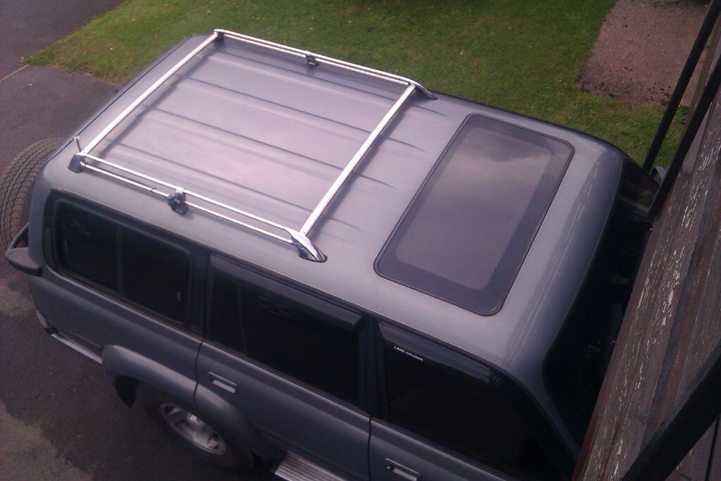
This one is for Chris, a picture I took a couple of weeks ago for someone else worrying about the bling bars on some later 80's
[attachment=0:1rta2pn3]IMAG1062.jpg[/attachment:1rta2pn3]
They are a bit bling and not particularly my cup of tea, shame we didn't get the black ones the NA market got but I expect some black paint could fix that According to the plate on the side they are rated for 75kg. Put the RT on these OEM bars and a couple of gutter mounted bars with a platform over the front part of the roof and it's about the same as a rack but not as heavy.
[attachment=0:1rta2pn3]IMAG1062.jpg[/attachment:1rta2pn3]
They are a bit bling and not particularly my cup of tea, shame we didn't get the black ones the NA market got but I expect some black paint could fix that
Attachments
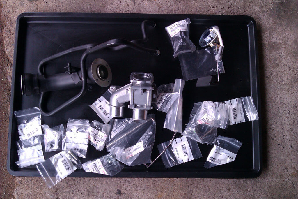
More progress on the aux tank install today. First job was cutting the end off the main tank filler pipe so that the dual filler neck could be fitted and then assembling the new filler. Here's the pile of bits for the new filler
[attachment=5:35dpcvp4]IMAG1092.jpg[/attachment:35dpcvp4]
turns into this
[attachment=4:35dpcvp4]IMAG1093.jpg[/attachment:35dpcvp4]
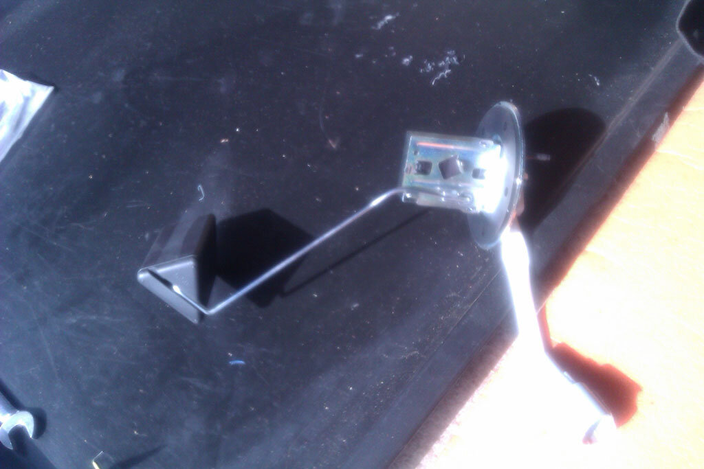
you have to bend the level sender float arm so it will read full for anything above about half a tank and below that start going down to an empty reading. You could make the float arm longer and get close to a proper full to empty reading but too much trouble. Once the gauge starts to budge you know you're down to your last 83l or so
[attachment=3:35dpcvp4]IMAG1094.jpg[/attachment:35dpcvp4]
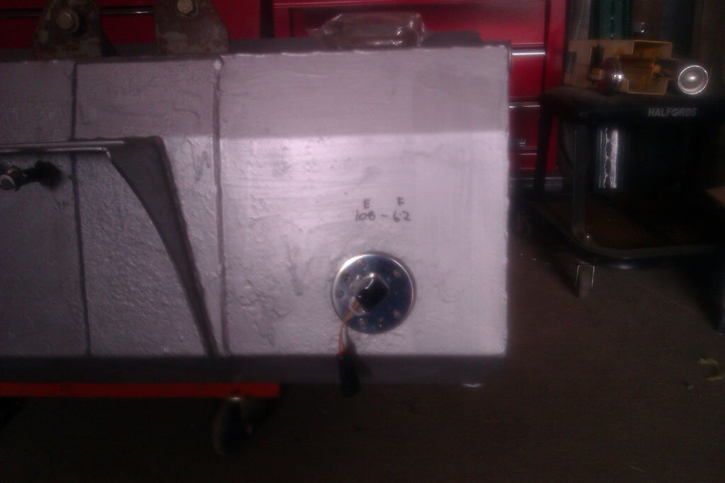
I changed the connector to an aftermarket waterproof connector because I don't have an OEM tail to match the connector it came with, measured empty and full resistance and made a note of it
[attachment=2:35dpcvp4]IMAG1096.jpg[/attachment:35dpcvp4]
Nearly time to fit the tank
[attachment=1:35dpcvp4]IMAG1098.jpg[/attachment:35dpcvp4]
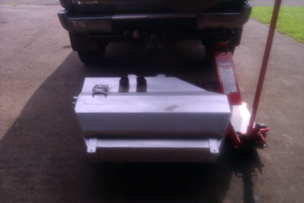
Fitted, not sure why the camera got so upset
[attachment=0:35dpcvp4]IMAG1099.jpg[/attachment:35dpcvp4]
Not too hard a job but not a simple / easy one either, if you've paid someone to fit one of these for you I'd say they probably earn't their money!
[attachment=5:35dpcvp4]IMAG1092.jpg[/attachment:35dpcvp4]
turns into this
[attachment=4:35dpcvp4]IMAG1093.jpg[/attachment:35dpcvp4]
you have to bend the level sender float arm so it will read full for anything above about half a tank and below that start going down to an empty reading. You could make the float arm longer and get close to a proper full to empty reading but too much trouble. Once the gauge starts to budge you know you're down to your last 83l or so
[attachment=3:35dpcvp4]IMAG1094.jpg[/attachment:35dpcvp4]
I changed the connector to an aftermarket waterproof connector because I don't have an OEM tail to match the connector it came with, measured empty and full resistance and made a note of it
[attachment=2:35dpcvp4]IMAG1096.jpg[/attachment:35dpcvp4]
Nearly time to fit the tank
[attachment=1:35dpcvp4]IMAG1098.jpg[/attachment:35dpcvp4]
Fitted, not sure why the camera got so upset
[attachment=0:35dpcvp4]IMAG1099.jpg[/attachment:35dpcvp4]
Not too hard a job but not a simple / easy one either, if you've paid someone to fit one of these for you I'd say they probably earn't their money!
Attachments
261l or there abouts, or about 1500 miles at autoroute speeds solo, more like 1300 with the caravan. There is no in tank pump on a diesel 80 (or 100) the IP on the engine has a lift pump built in so it just sucks on the pipe. I have some OEM valves to install, shown in an earlier post, which when powered will divert sucking to the aux tank. I am also fitting a walbro pusher pump, more for its self priming ability than pumping, so if I run a tank dry it will force fuel up to the IP instead of manually priming the system. The pusher pump will take the load off the IP lift pump as well though which can't be a bad thing.
Sent from my HTC ChaCha A810e using Tapatalk 2
Sent from my HTC ChaCha A810e using Tapatalk 2
I will post some more pics later but considering the capacity of the tank it tucks up really neatly and leaves better ground clearance than when the spare was under there, by quite a bit.
Sent from my HTC ChaCha A810e using Tapatalk 2
Sent from my HTC ChaCha A810e using Tapatalk 2
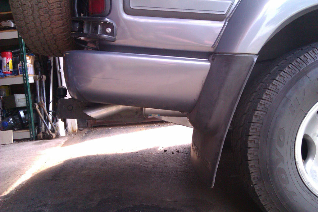
Done some finishing off and tidying up of the aux tank install today. I had to revisit the filler because the hoses weren't sitting right and were kinked. I had assumed that as the hoses and filler are OEM and the tank replaces an OEM part simply fitting the hoses would see the filler in the correct position and then I'd make the bracket to fix it in place. Not so, I ended up cutting 60mm from the tank end of the hoses and then I could fix the filler in a position where the hoses were ok. It would be much easier with the OEM bracket to fix the filler in place but the only part number I've found is for an older style filler. Anyway, got there in the end with a bit of fiddling and you can see the bracket I made to support the filler which fixes to an existing captive nut on the body.
[attachment=6:1bw61oqi]IMAG1104.jpg[/attachment:1bw61oqi]
The business end, knob down as shown here to fill main tank as normal, pull the knob out to fill the aux tank
[attachment=5:1bw61oqi]IMAG1105.jpg[/attachment:1bw61oqi]
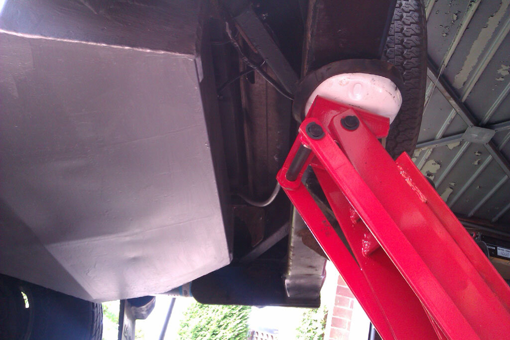
The tank is quite short and leaves quite a bit of space to the rear cross member
[attachment=4:1bw61oqi]IMAG1107.jpg[/attachment:1bw61oqi]
Really well tucked up out of the way considering its capacity
[attachment=3:1bw61oqi]IMAG1108.jpg[/attachment:1bw61oqi]
[attachment=2:1bw61oqi]IMAG1112.jpg[/attachment:1bw61oqi]
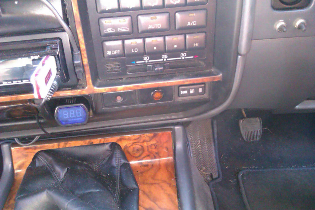
OEM switch to select running from the 'sub' tank wired up and installed
[attachment=1:1bw61oqi]IMAG1115.jpg[/attachment:1bw61oqi]
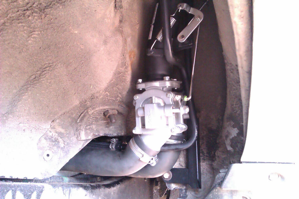
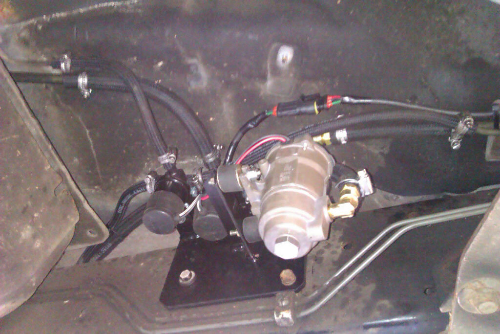
Here you see the pump and valves in place and plumbed in. Towards the top left is the OEM metal pipe run to the main tank which I have cut and connected to the valves, bottom left ish is the run of pipe going to the aux tank and to the right are the pipes that feed back onto the OEM metal pipes running to the filter and IP in the engine bay as normal. For electrickery I've run a 3 core cable with a single 3 pin water proof connector. I thought about 1 connector for each of the valves and another for the pump but if any one of those is giving trouble I would take the hole unit off the truck to get a better work position so I think 3 connectors would have been OTT. 2 of the cores go to the power outlet by the driver side battery for earth and IGN + for the pump so it runs whenever the ignition is on. The 3rd core goes to the dash switch and powers the valves when selected.
[attachment=0:1bw61oqi]IMAG1116.jpg[/attachment:1bw61oqi]
I haven't connected the aux tank level sender to anything yet. I may connect it to the existing dash gauge via a relay to switch between showing main and aux but ideally I'll get another Arduino gadget built soon and connect it to that instead. I've run around in the truck this afternoon since connecting it all up and there were no leaks so now I just need to put some fuel in the aux tank so I can check running from that is ok, check for leaks at the filler and then I can put the cover panel back over the filler inside the wheel arch
[attachment=6:1bw61oqi]IMAG1104.jpg[/attachment:1bw61oqi]
The business end, knob down as shown here to fill main tank as normal, pull the knob out to fill the aux tank
[attachment=5:1bw61oqi]IMAG1105.jpg[/attachment:1bw61oqi]
The tank is quite short and leaves quite a bit of space to the rear cross member
[attachment=4:1bw61oqi]IMAG1107.jpg[/attachment:1bw61oqi]
Really well tucked up out of the way considering its capacity
[attachment=3:1bw61oqi]IMAG1108.jpg[/attachment:1bw61oqi]
[attachment=2:1bw61oqi]IMAG1112.jpg[/attachment:1bw61oqi]
OEM switch to select running from the 'sub' tank wired up and installed
[attachment=1:1bw61oqi]IMAG1115.jpg[/attachment:1bw61oqi]
Here you see the pump and valves in place and plumbed in. Towards the top left is the OEM metal pipe run to the main tank which I have cut and connected to the valves, bottom left ish is the run of pipe going to the aux tank and to the right are the pipes that feed back onto the OEM metal pipes running to the filter and IP in the engine bay as normal. For electrickery I've run a 3 core cable with a single 3 pin water proof connector. I thought about 1 connector for each of the valves and another for the pump but if any one of those is giving trouble I would take the hole unit off the truck to get a better work position so I think 3 connectors would have been OTT. 2 of the cores go to the power outlet by the driver side battery for earth and IGN + for the pump so it runs whenever the ignition is on. The 3rd core goes to the dash switch and powers the valves when selected.
[attachment=0:1bw61oqi]IMAG1116.jpg[/attachment:1bw61oqi]
I haven't connected the aux tank level sender to anything yet. I may connect it to the existing dash gauge via a relay to switch between showing main and aux but ideally I'll get another Arduino gadget built soon and connect it to that instead. I've run around in the truck this afternoon since connecting it all up and there were no leaks so now I just need to put some fuel in the aux tank so I can check running from that is ok, check for leaks at the filler and then I can put the cover panel back over the filler inside the wheel arch
Attachments

Graham
Well-Known Member

Great job there Jon, and well illustrated by the photos.
I am sure you must have took many photos, and picked the best one to show us all.
So,,,,,,,,260 liters or there about.
How about keep the original tank for deal diesel, and the sub tank for low price heating oil, when you are abroard?
Gra.
I am sure you must have took many photos, and picked the best one to show us all.
So,,,,,,,,260 liters or there about.
How about keep the original tank for deal diesel, and the sub tank for low price heating oil, when you are abroard?
Gra.