Don't like the adverts?  Click here to remove them

Hedgehog - LC100 build thread

Here's my Glind mounting in the engine bay.
Mounted mine on the inlet manifold as its easier to get at the heater plumbing there. To the right you can see the water pump.
The HE water i/o connections are via garden hose click lock fittings underneath the front Roo bar.
Strongly suggest that you use at least three if not the four mounting tabs. If you use just two, eventually they'll snap with vibration. Bit of weight there with the water and copper.

glind1.jpg


glind2.jpg


You can see some of the heater hose routing here-
Out of the block into the H/E
glind4.jpg


HE return to cabin heater.
glind5_1.jpg


Thanks Womblingfree.....I'll take a look at that fitting option. I didn't even try that as I thought there would be insufficient space under the bonnet.
 
Thanks Womblingfree.....I'll take a look at that fitting option. I didn't even try that as I thought there would be insufficient space under the bonnet.

The only height issue was with the inline tap (yellow handle). I had to bend its support bracket down a bit as the handle was rubbing against the bonnet sound deadening material.
 
Quick update on the WiFi range extender/active antenna/private hot-spot now being held in place by the RAM mount. This is shown in the upright position when we are stationary, when we're moving I can fold it down level with the rack if I wish


View attachment 18345

Im very interested in this setup. How did you mount the other part of the system? How do you like like it so far? Thanks
 
Im very interested in this setup. How did you mount the other part of the system? How do you like like it so far? Thanks

So far I've been very pleased with how it works and the simple set-up/operation out of the box with clear instructions.

In terms of where I've put the other end (ie the router/personal hot-spot) I plan to permanently mount the unit to the underside of the high level shelf (I haven't done this yet as I'm waiting for the proper version to be made). This gives unobstructed coverage in the truck and around camp. Other locations that I considered included some space between the internal plastic panels and the outer skin near the jack; or mounted to the underneath of the wooden wings in the rear drawer system. Both would have affected coverage in the truck or camp. The unit as supplied comes with a decent length of cable to link the antenna to the router. The whole system has a small power block that plugs into a standard cigarette lighter socket, the wire for which is about a meter long. I will soon cut off the 12v plug and permanently link (switched and fused) to permanent 12v so that this can be powered without the ignition switched to AUX. The router is quite small and light weight so you could find a lot of mounting locations for it.......but the power unit will need to be protected from knocks

By the way the antenna can be fixed to a window internally or externally using the 4 supplied suckers but with a small compromise in range performance
 
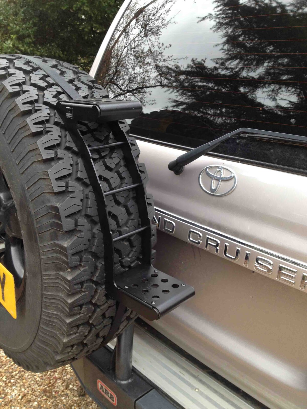
Front Runner spare tyre step ring now added to help with access to the roof rack if I need to actually get up there

IMG_1525 low res.jpg
 
Don't like the adverts?  Click here to remove them
Good progress


Sent from my iPad using Tapatalk
 
Good progress


Sent from my iPad using Tapatalk

Thanks Andy. I should be able to report a lot more progress this week as there are a lot of things each waiting for a little loose end to be finalised before I can complete/commission.
 
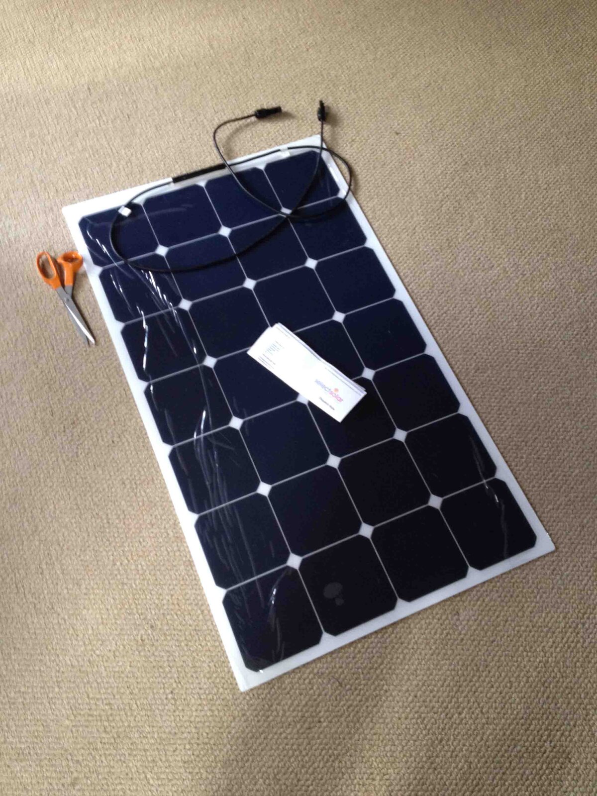
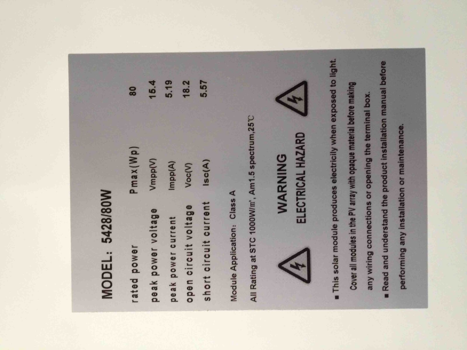
80W solar panel arrived today. This will mount to a slide out tray on the roof rack which will also contain the charge controller (outdoor/potted unit). A flying lead will then connect to the battery. The idea is for the tray to either be slid most of the way out (when parked up :) ) or removed from the slides and put on the ground to point directly at the sun. The solar panel is semi-flexible and does not come with the glass/surrounds and thus weight. Waiting for the aluminium to arrive so I can fabricate the tray. The panel will be stuck down with silicone sealant

IMG_1539 low res.jpgIMG_1540 low res.jpg
 
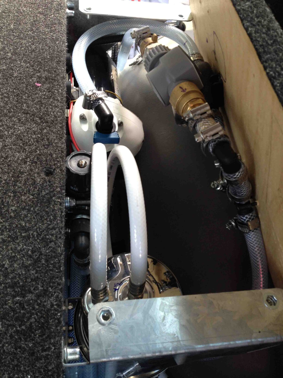
Final commissioning of the water filtration/water pump/metering/pipework today. apart from a couple of weepy hose clips the system was commissioned successfully. The only real issue last week in pre-commissioning was that the water metering device could not hold a vacuum with a head of more than about an 1" and I had to find another device. It wasn't so much the device but it was its connections which I could only use the quick connect garden hose type. I was warned that these were no good under vacuum as was proved to be the case here, allowing the pump to suck air in via the push-fit O-ring. So with a different water meter I can now use more robust high pressure fittings that have fixed this particular issue. The pictures below show the various views of the system and commissioning.

The completed system packaged under the side wing
IMG_1546 low res.jpg

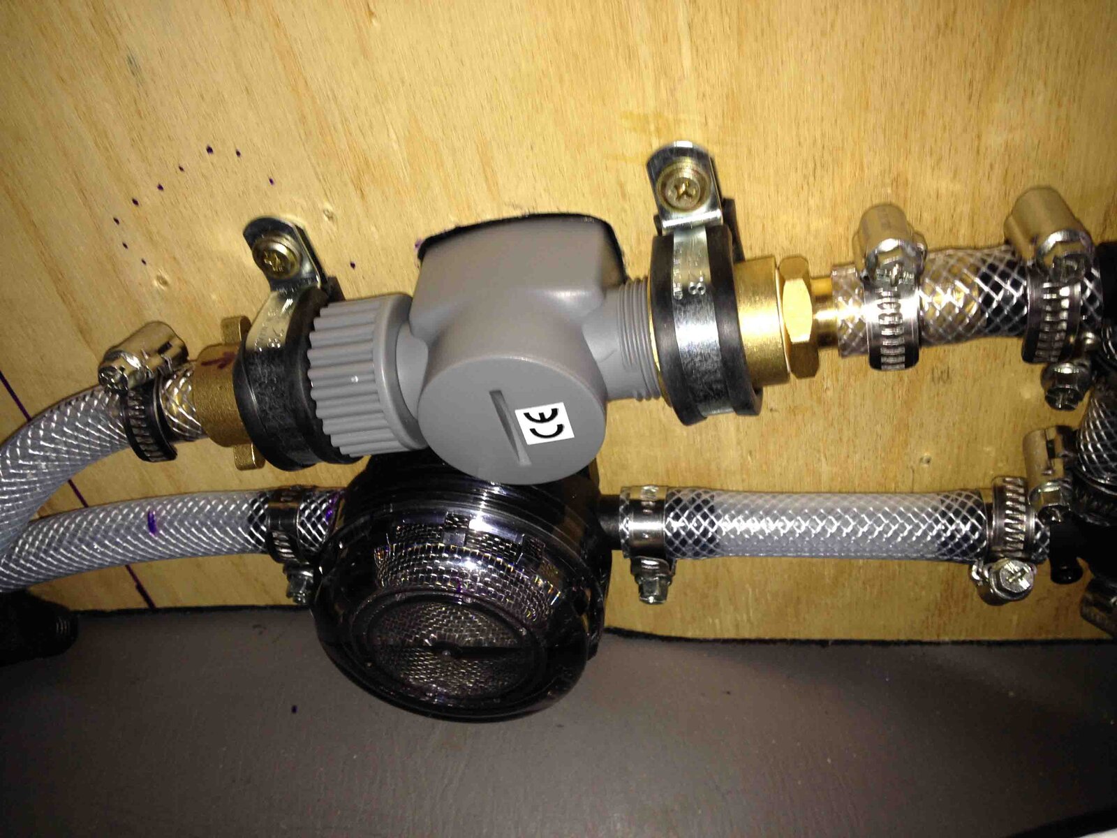
Detail of the underside showing pump screen filter and water meter
IMG_1555 low res.jpg

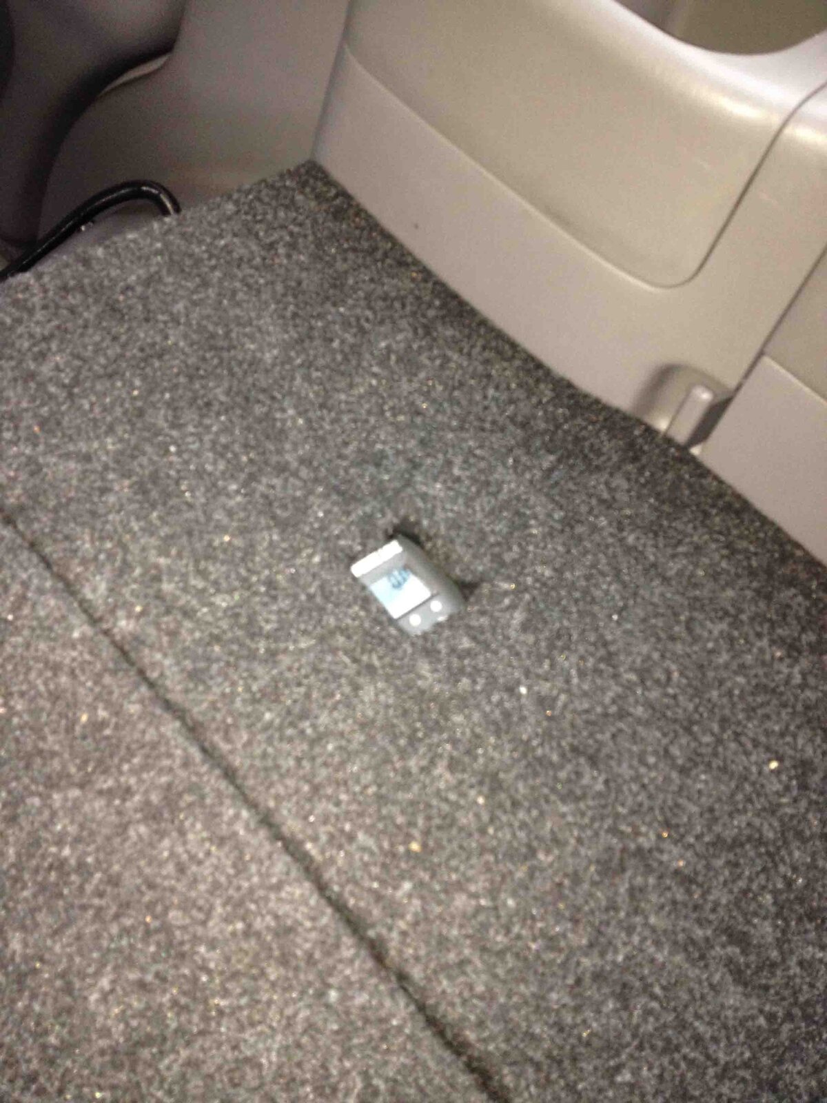
The recessed water meter display and reset buttons
IMG_1557 low res.jpg

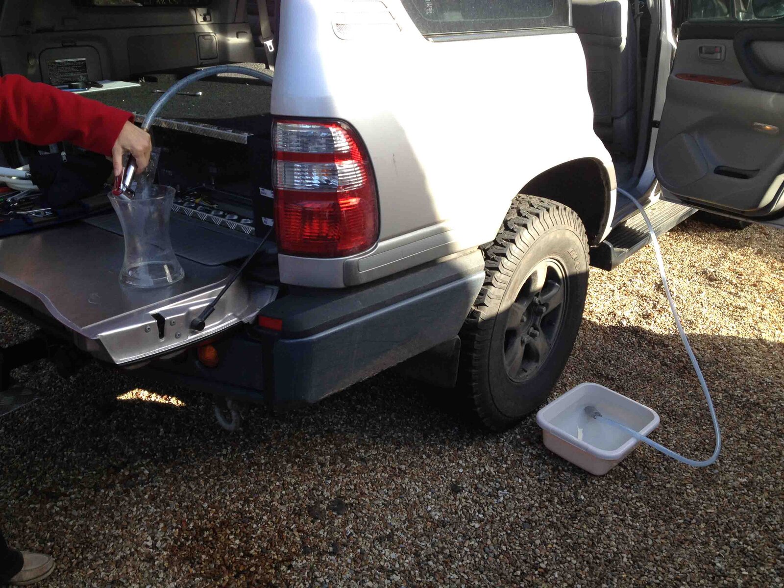
Using the sand spear in a bucket to simulate a tank of water and to test the ability of the system to prime. This only about a meter of height....the pump should do nearly 2.9m....I'll test that down by a river at some point
IMG_1551 low res.jpg

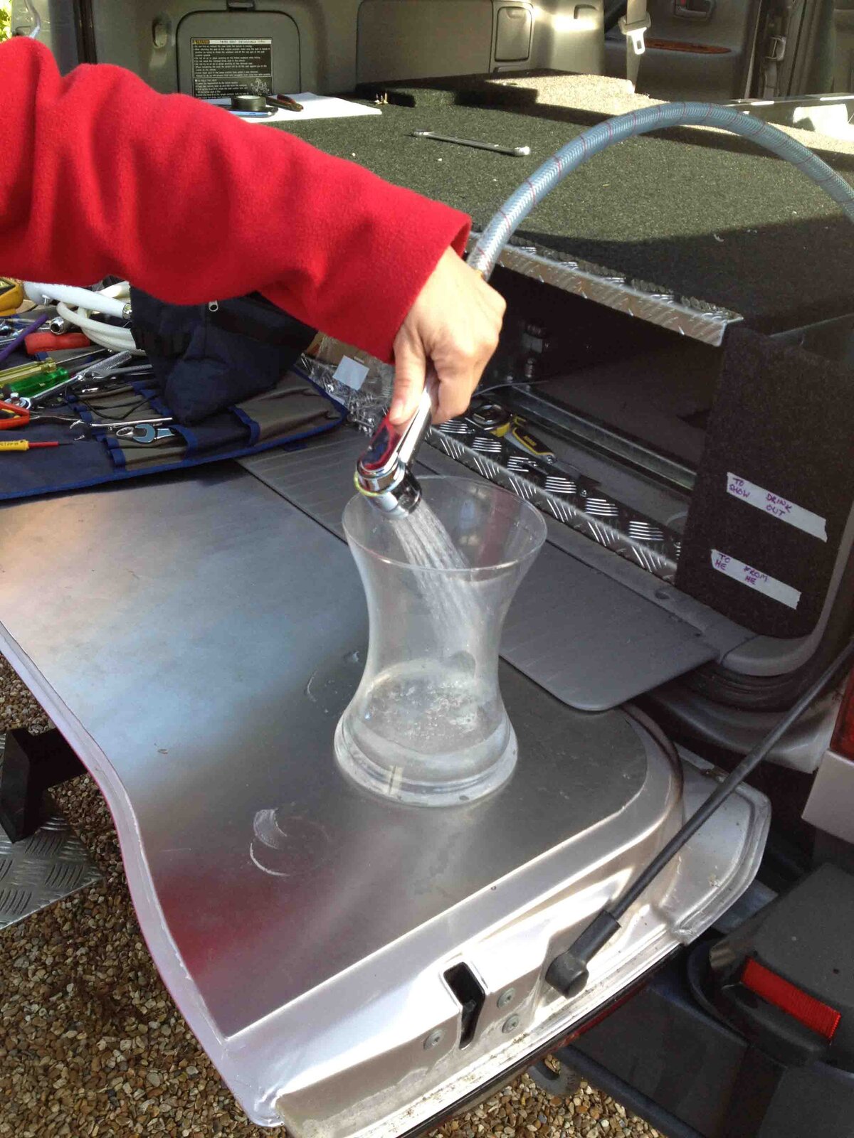
Clean drinking water out of the Seagull IV filter.....tea anyone?

IMG_1554 low res.jpg
 
Last edited:
That water meter is a good idea to monitor usage, I use a bit of dowel I have to stick through hole I. Tank at moment... Where did you source the meter, I assume it is battery powered ?


Sent from my iPad using Tapatalk
 
That water meter is a good idea to monitor usage, I use a bit of dowel I have to stick through hole I. Tank at moment... Where did you source the meter, I assume it is battery powered ?


Sent from my iPad using Tapatalk

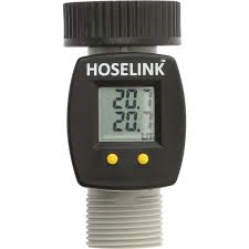
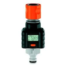
I got it off Amazon for £18.....lots of variants of the same looking thing, just different branding. DONT buy the one in the photo below with the orange fittings - I couldn't get this to have a reliable connection due to the way the threads are constructed (not many turns and has a flange on one side)

It uses a button battery - you can see the compartment on the pictures of the underside

This one or variants....


Revised water meter.png

NOT this one...
 

Attachments

  • wrong water meter.png
    wrong water meter.png
    29.4 KB · Views: 373
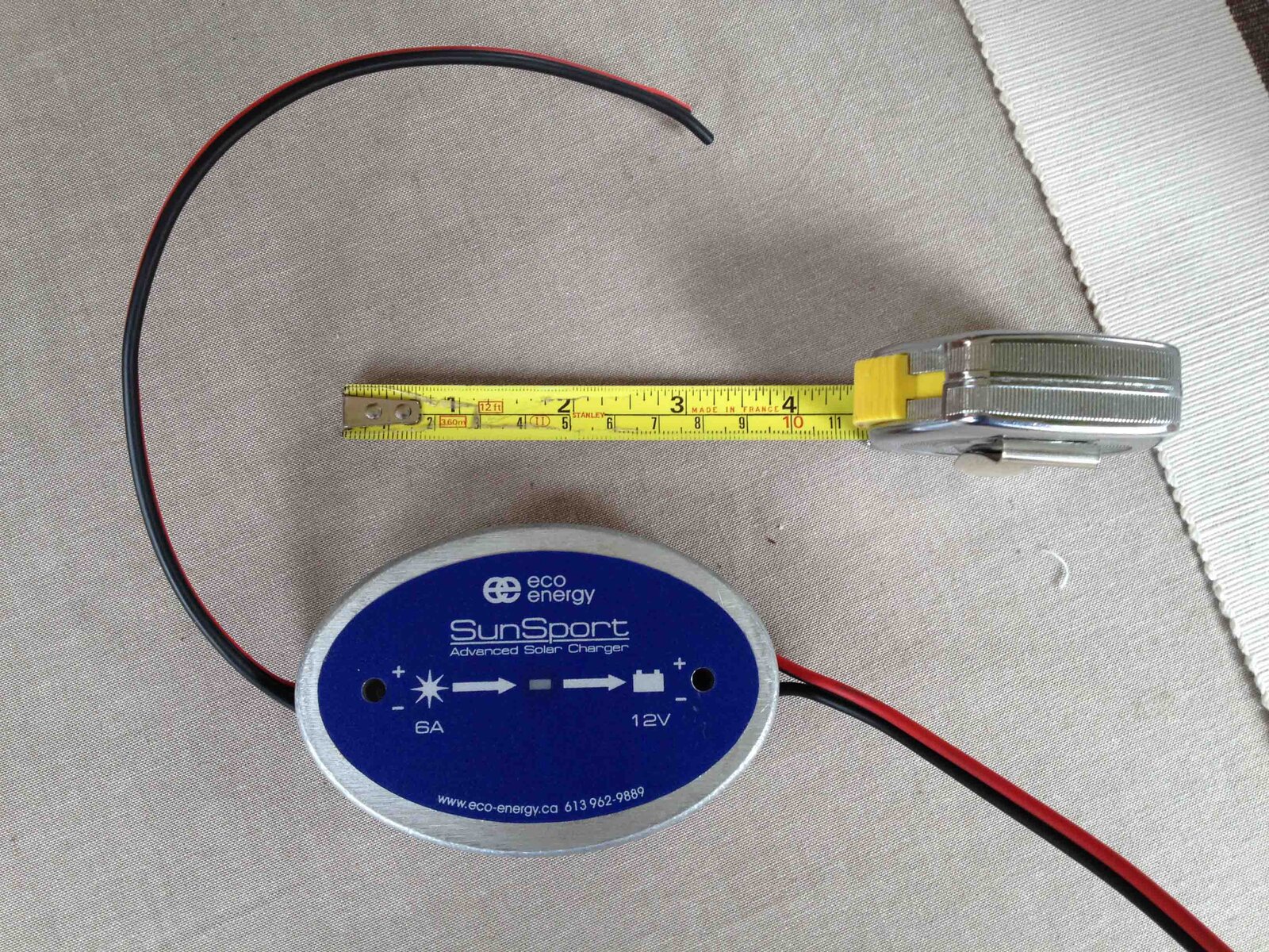
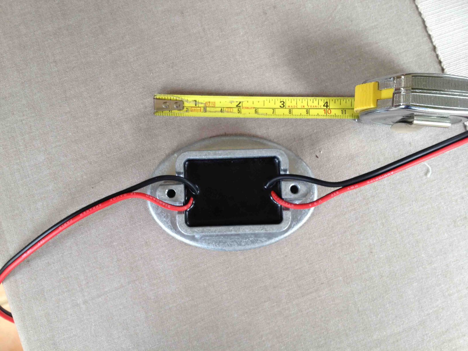
Solar charge controller arrived. Looks good and robust cast housing and nicely potted to keep the rain out. Still waiting for the ally tray to arrive before I can put this all together. Looks like there is potential for the 12v wires to short to the tray with a bit of wear and tear so I'll have to sort that element out with some trunking, sleeving and clips

IMG_1559 low res.jpg


IMG_1560 low res.jpg
 
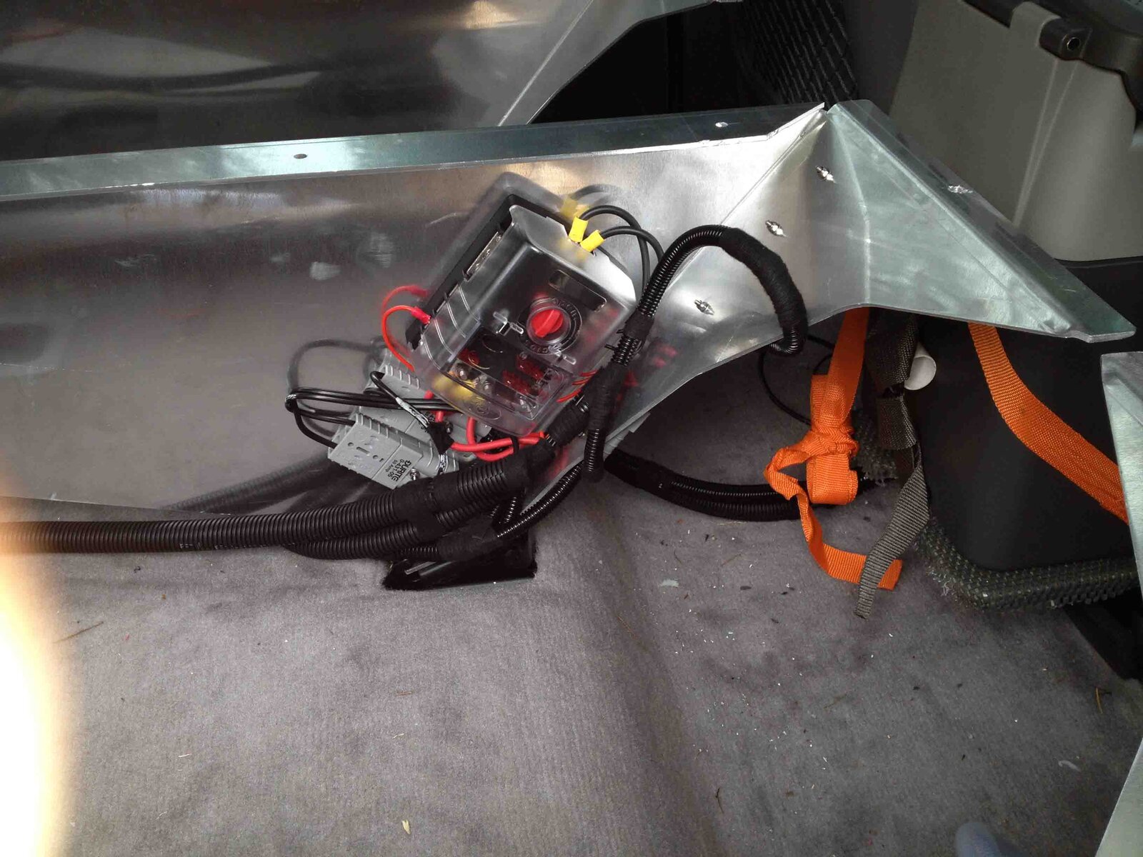
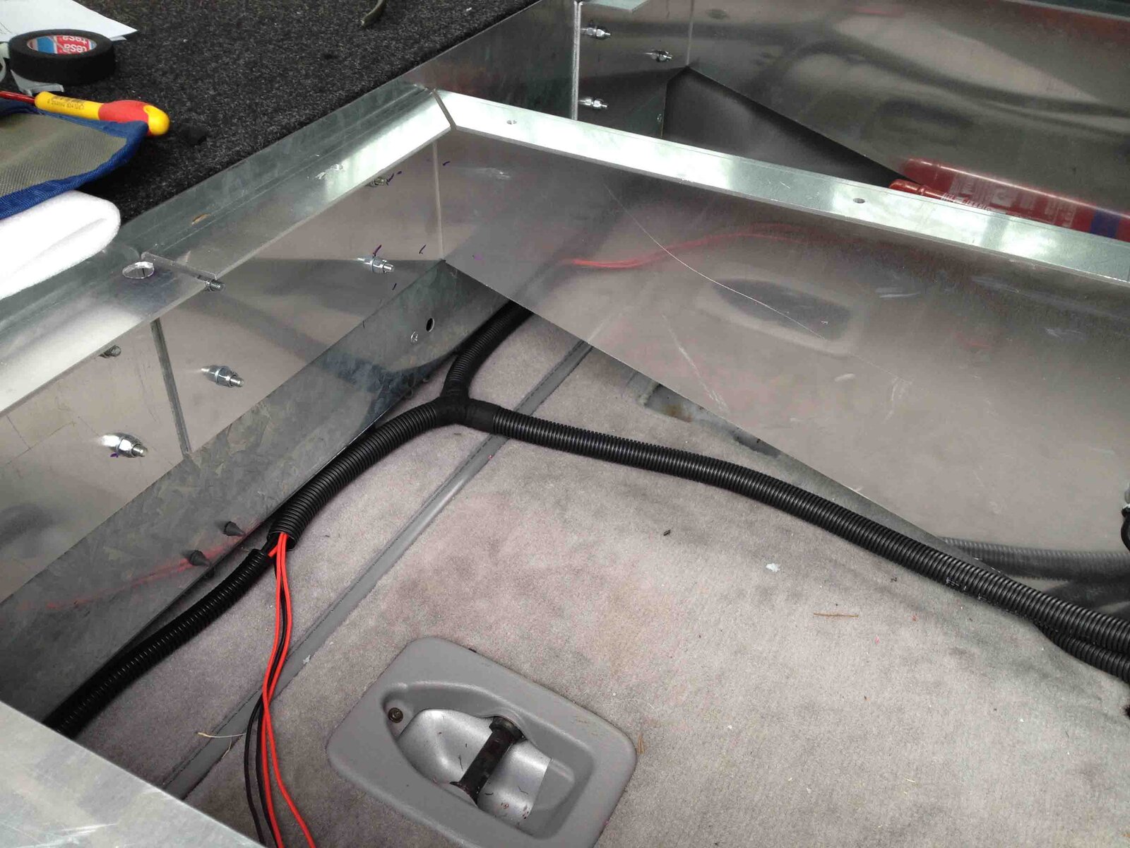
Electrics now finalised with an additional fuse and distribution block mounted under the extended floor. Circuits for WiFi, Water Pump, and 2 prepared circuits for the water tank/water system defrost heaters which will be fitted later (the two loose tails). All these circuits are fed by an isolating relay from what will be the auxiliary battery (once the split charge controller is in). Also in this area are 3x Andersons one each for the fridge and freezer and one for high power general use (front row seat area). There is also a standard cigarette lighter socket and dual USB power, both accessible from behind the front passenger seat for equipment chargers to augment the two 12v sockets in the centre dash.


IMG_1564 low res.jpgIMG_1565 low res.jpg

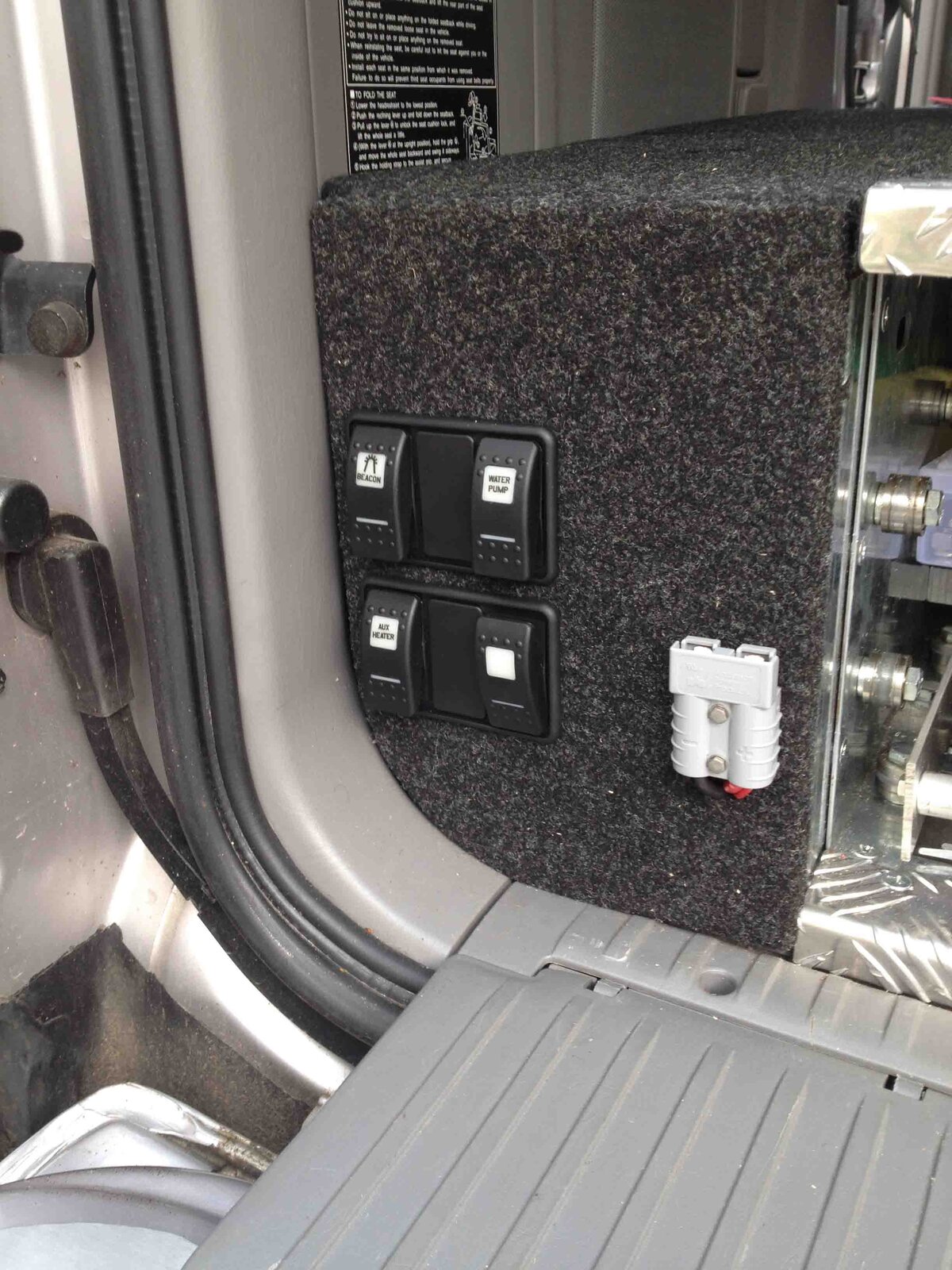
The Carling switches are mounted on the rear side wing and easily accessible with the tail gate down. This position also provides some protection from being knocked when the tailgate is up but the switches can still be operated if we're sleeping inside the car (e.g. to turn off the wifi). I've segregated the switches into 2 groups - the rarely used tank defrost circuits in the lower group and the day-to-day wifi and water pump in the upper group. I've added a couple of blank positions in case I want to add extra circuits like work lights or camp lighting later. Also on the rear panel is a 50A Anderson for my 12v drill or the missus hair dryer.

IMG_1590 low res.jpg

I've set up the switch back lighting to be on when the circuits are primed (ie the isolating relay is on, rather than with sidelights) and to illuminate red when each switch is ON. This will be a simple tell-tale that the permanent relay isolated circuits are still on and will help remind me to turn everything off at night should I need to.
 
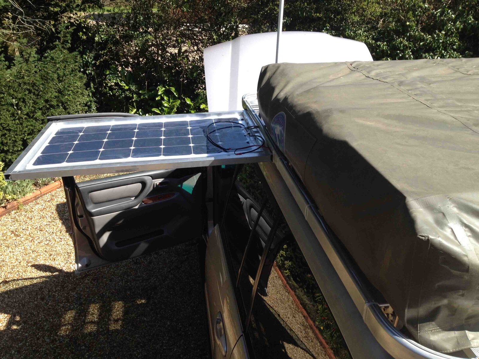
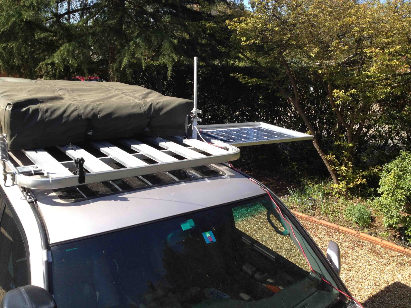
Completed making the frame for the solar panel. The frame is 25mm square aluminium tube and is riveted to the alloy sheet. This fits neatly into the C channels on the roof rack that originally held the slide out table. To connect the various components together I will use the same connector style that is used on Ctek chargers (and cut off the single pole connectors supplied with the panel). These can be bought with a number of different connections to cigarette lighter, ring terminals, croc clips etc to give a number of options. Longer term I will install a waterproof rotary switch in the engine compartment so that I can route the solar charge to either battery (I want to charge the starter battery if the truck is laid up for a while, but I will charge the leisure battery when camping). The solar panel can be slid 3/4 of the way out of the rack slide or detached from the truck and propped up on the ground so the normal way of connecting the panel will be with a (Ctek) flying lead to a socket behind the bumper.

IMG_1596 low res.jpg
 
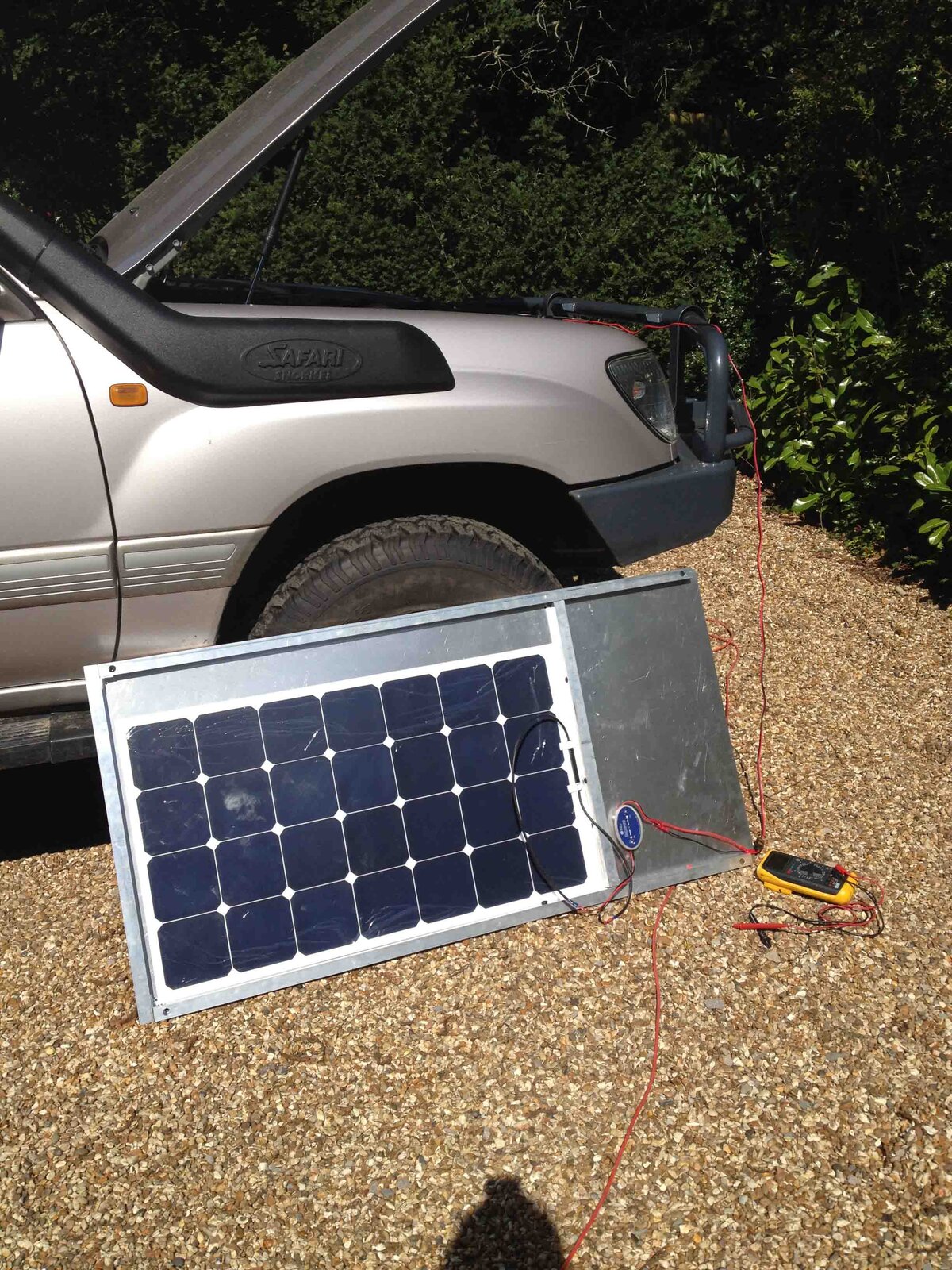
Commissioning the solar panel. Still need to glue down the panel and secure the wires, but the system is now electrically commissioned and earning its keep in the sunshine


Off vehicle charging
IMG_1598 low res.jpg

On vehicle charging
IMG_1600 low res.jpg


IMG_1602 low res.jpg
 
2nd spare wheel now mounted up on the roof. Space very limited so had to move the roof tent back 2" and decided to form up a retaining plate for the wheel due to the overhang. Whilst the roof would not be my preferred option for another 35kg (as the rack and RTT weigh 74kg) it does mean that I can avoid the weight of a second wheel carrier on the rear bumper (the carrier alone is 25kg).....this is plan B. There are other options. For example I have room to put the spare onto the flat load bed inside the truck, but this means emergency sleeping will mean moving the wheel out of the way. I could have just the spare tyre only on the roof - but this saves a measly 11kg for the wheel - and then have the hassle of tyre levers if I need to use it.

I'm not overly concerned about weight up high as the bulk of the truck's 3 tons is low down

IMG_1607 low res.jpg
 
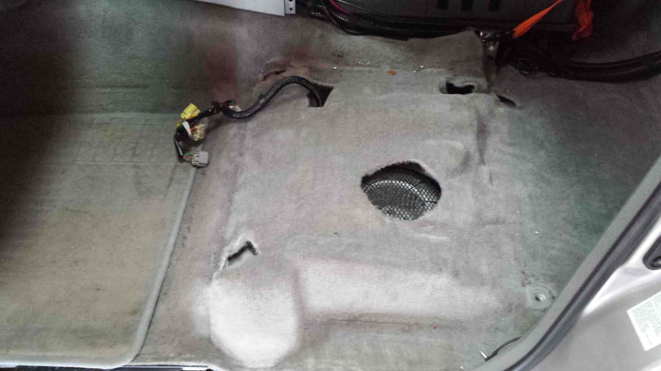
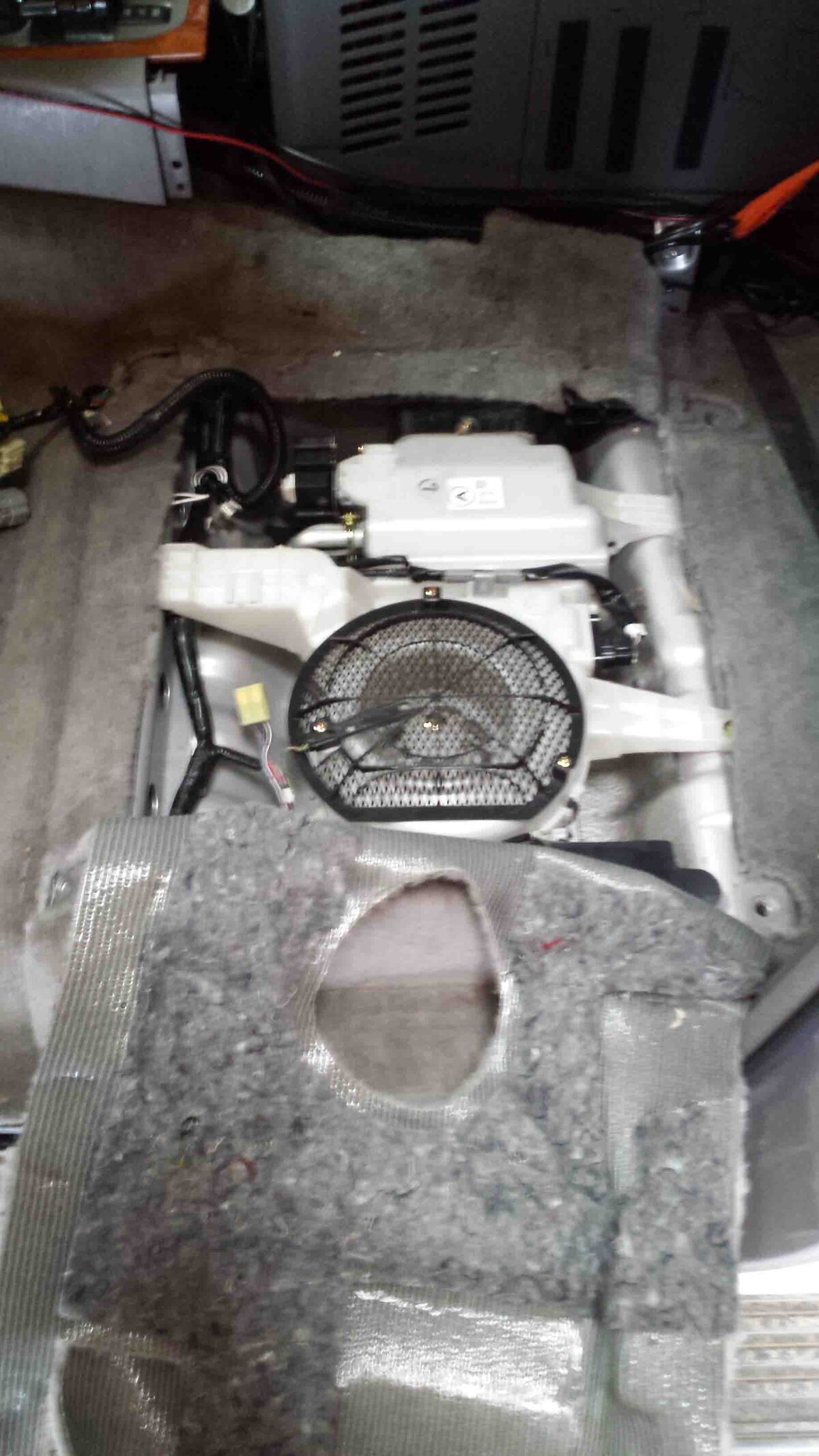
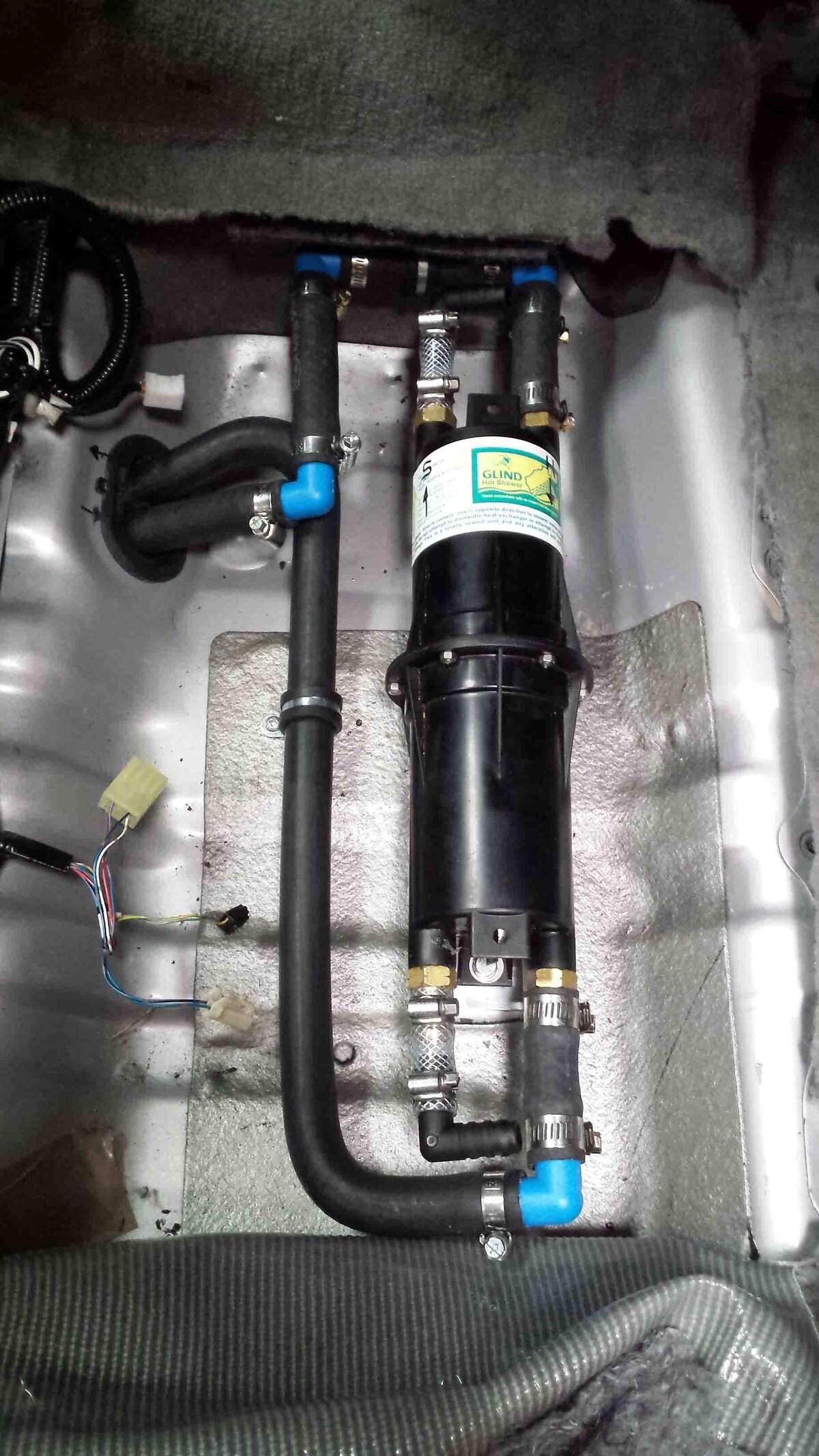
Been moving forward with the heat exchanger Glind installation under the front passenger seat. This makes use of existing run of pipes from the engine bay to the middle of the truck. There are some photos above of what the pipes look like under the truck. The rear heater is no longer required on our truck so is surplus to requirements, and a useful weight saving too. I looked at Womble's suggestion to mount the HE on top of the rocker cover but there is no space there and too many other things get in the way (UK model truck)

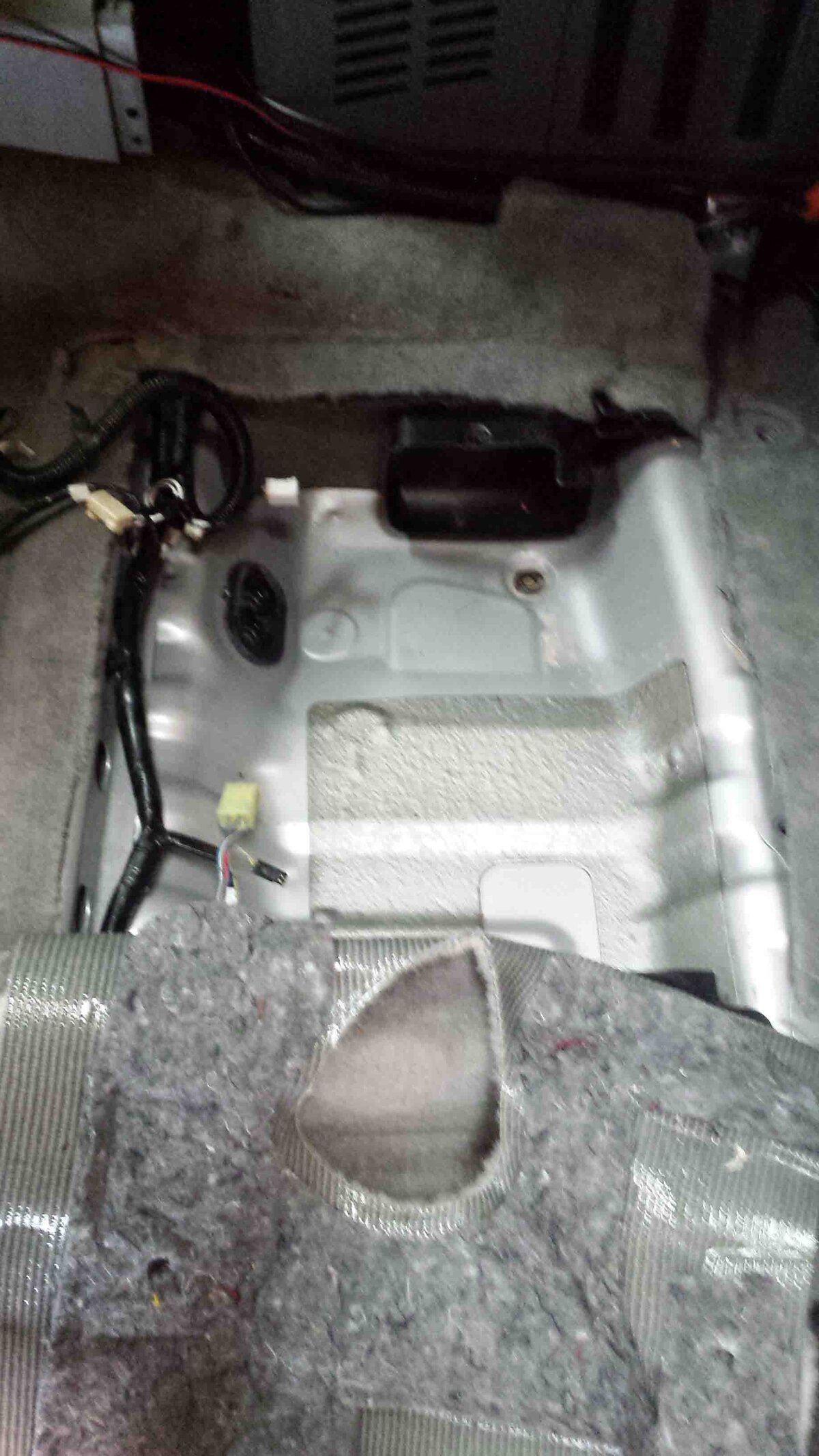
The space under the passenger seat

20150519_114754 low res.jpg


Carpet cut back showing the heat exchanger assembly (includes a blower)

20150519_120244 low res.jpg


The assembly removed leaves a pretty large space which could be used for a number of purposes

20150519_123318 low res.jpg


The Glind in place commissioned on the engine side but still needs to have the shower water side piped in to the barbed ends. The entry points into the car use an existing rubber gland so no extra holes and nicely sealed against water ingress

20150520_151335 low res.jpg
 
Very nice. My only thought is that by the time the water gets there from the engine has it not cooled too much to give you piping hot water or is there sufficient heat still to heat your water.

No blower means no rear heater system or AC is my understanding as the blower serves end the rear of the car.

Some good points there Warren. I thought about the extra length on the engine feed side - it is about 3ft of extra pipe run. With the engine stable at say 82C even with a bit of extra loss and allowing for a bit of inefficiency in heat exchanger conversion I am GUESSING that the 60C thermostatic mixing valve on the shower side will just be closing.....time will tell. I know that the boys over at Glind said that they had heard of mixed results with it in this location. If the extra losses on the pipe run are excessive then I can always lag the runs with foam or aluminium tape.

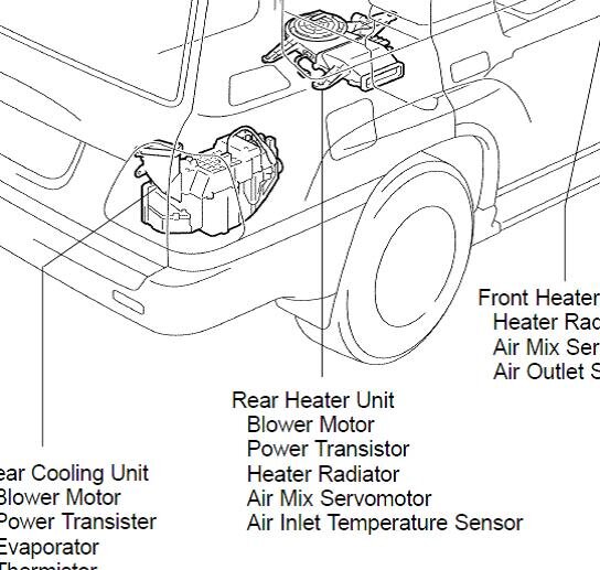
In terms of the heater and air con issue then if this Toyota drawing is to be believed then the a/c blower and heat blower are two different things - the a/c blower seems to be in the rear quarter??


Land Cruiser Rear Heater Position.jpg
 
Back
Top