Don't like the adverts?  Click here to remove them

LJ70 Build Thread!

Thanks Edward. :thumbup:

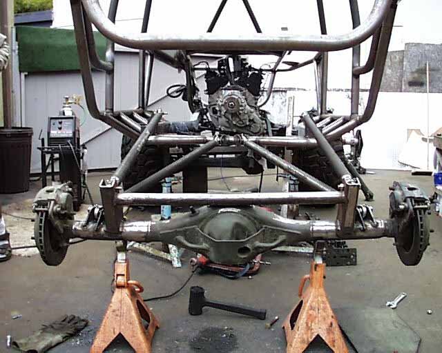
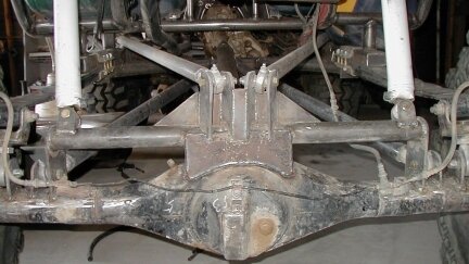
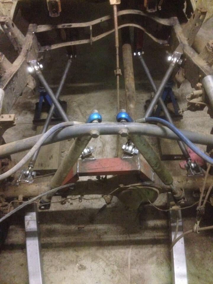
The prop shaft has a long floating section where it goes into the transfercase with splines.

I'm actually thinking of fitting a double cardon prop though to help with the extreme angle of the shaft. :think:

Obviously its not going to be able to have quite as much articulation as in the pics above as the tyres hit the chassis. The length of shocks and a combination of longer bump stops and/or limiting straps might have to be fitted.

I think it will flex a little differently though once the weight of the cage, fuel cell, seats, center winch, etc. go on.

Having never done something like this before, it is very experimental for me and I really dont know how well it will work. :think:

Forgot to add above.............................

The top of the welding trolley is being kept clear for a water cooler for a water cooled TIG torch. One of these. :icon-cool:

https://www.millerwelds.com/pdf/spec_sheets/AY7-2.pdf
 
The prop angle does look a bit extreme, I wondered about dropping the GB mount down a touch to rake the engine/GB back a bit? A double cardon joint will help though. The "A" link looks ace! :thumbup:
 
Rear suspension looks good but I would be tempted to have the a frame running more level than that, needs more separation at the axle end and less at the chassis, should mean less rear steer when flexing :thumbup:
 
Great work ,
How will you help to guide the springs back onto the bump stops on rear axle ?
Because the springs were popping out on extreme articulation
Is that where he shocks and limiting straps will stop this happening ?


Sent from my iPad using Tapatalk
 
The problem with the "A" frame is that it is fundamentally flawed.

It just wont work.

If you look back a page or so to the photo of the original "A" frame you will see that the mountings to the chassis are in line. When mounted this way an "A" frame will move in an arc about it's mounting points. Ben has mounted his "A" frame at approx. 90 degrees to each other. As the "A" frame attempts to move, a twisting force will be set in motion that will attempt to crush the void bushes and then twist the mountings. Somewhere along the line, something will break. I would imagine that 25 mm would be the maximum movement at the axle before the void bush locks up and movement ceases.

Roger
 
Roger, do you mean that the "A" frame chassis mounts should have the same axis? It makes sense that for the apex of the frame to raise and lower, the pivots should be the fulcrum of the arc, i.e. on the same axis.

Ben could modify the set-up he has, by turning the chassis mounts to share the same axis.
 
Don't like the adverts?  Click here to remove them
Roger, do you mean that the "A" frame chassis mounts should have the same axis? It makes sense that for the apex of the frame to raise and lower, the pivots should be the fulcrum of the arc, i.e. on the same axis.

Ben could modify the set-up he has, by turning the chassis mounts to share the same axis.

Yes.

Roger
 
The prop angle does look a bit extreme, I wondered about dropping the GB mount down a touch to rake the engine/GB back a bit? A double cardon joint will help though. The "A" link looks ace! :thumbup:

That is a possibility but I was hoping to keep it all above the bottom of the chassis rails so I can bolt a nice thick (8-10mm) sheet of alluminium over the whole underside of the vehicle. :think:

Rear suspension looks good but I would be tempted to have the a frame running more level than that, needs more separation at the axle end and less at the chassis, should mean less rear steer when flexing :thumbup:

Thanks, thats interesting. :icon-smile:

I was trying to keep the angle of the bottom links and the top links/A frame similar as from what I had seen and read thats how they should be. :think:

Great work ,
How will you help to guide the springs back onto the bump stops on rear axle ?
Because the springs were popping out on extreme articulation
Is that where he shocks and limiting straps will stop this happening ?


Sent from my iPad using Tapatalk

Thanks Andy, not sure exactly yet but yes I can limit the droop with limiting straps, bigger bump stops and shocks.

I'd quite like it if the springs can dislocate slightly though. :think:

The problem with the "A" frame is that it is fundamentally flawed.

It just wont work.

If you look back a page or so to the photo of the original "A" frame you will see that the mountings to the chassis are in line. When mounted this way an "A" frame will move in an arc about it's mounting points. Ben has mounted his "A" frame at approx. 90 degrees to each other. As the "A" frame attempts to move, a twisting force will be set in motion that will attempt to crush the void bushes and then twist the mountings. Somewhere along the line, something will break. I would imagine that 25 mm would be the maximum movement at the axle before the void bush locks up and movement ceases.

Roger

Thank you Roger, I can see what you're saying. :think:

So maybe I can do as Clive suggested and alter the chassis mounting ends of the A frame and chassis mounts. The brackets on the chassis are only tacked so their easy enough to alter and the A frame can easily be cut at the correct angle in the Brobo saw and re-notched and welded. :icon-biggrin:

I dont mind having to alter things as like I said previously, this is the first time I've done anything like this so its a bit experimental for me. :thumbup:
 
I'd agree with Roger on the A frame mounts. There is mountains of info on suspension design on the web it's worth a read

Is it just me or is the diff angled up? It will be better if it isn't as props shaft flanges need to be parallel - ever at big angles - There are videos on you tube explaining this and showing the weird phasing that occurs

ive been here before, it's shocking how much stress suspension arms are under even on a small rig - snapped big Rose joints bent stuff etc etc

When I modified my Vitara years ago I relocated the A frame mount to the axle case this made the arm angles more acceptable and as a bonus it made Diff swaps much less hassle.
 
Thanks. :icon-biggrin:

I have done quite a bit of research online and just looking now I've spotted a lot of setups that have their A frames/top link mounts running at angles like mine. :think:
 

Attachments

  • crig4006.jpg
    crig4006.jpg
    50.3 KB · Views: 385
  • rear4link1.jpg
    rear4link1.jpg
    84.4 KB · Views: 401
  • toyota 75 4 link rear.jpg
    toyota 75 4 link rear.jpg
    76.9 KB · Views: 503
None at quite the angle of yours through, top one is in droop, also a 4 link behaves differently when articulating than a 3 link A frame set up
 
I note that in the above photos, they seem to be using fully articulating rose joints (if that's the right term) and not void bushes, which don't have as much flexibility. Just an observation Ben.
 
An "A" frame is a rigid structure that moves up and down and requires the chassis mountings to be in line. The pictures show 4 link systems where each link is a separate unit fitted with rose joints. These joints allow for a much greater movement than a simple void bush.

If you disconnect the rose joint from the Jimny axle and attempt to move it up and down you will get a few mm of movement before the void bushes "lock up" ie the inner tube twists and hits the outer tube. Then any further movement will twist the "A" frame or chassis.

Roger
 
Thanks guys, will have another look at it this week hopefully. :thumbup:
 
The problem with the "A" frame is that it is fundamentally flawed.

It just wont work.

If you look back a page or so to the photo of the original "A" frame you will see that the mountings to the chassis are in line. When mounted this way an "A" frame will move in an arc about it's mounting points. Ben has mounted his "A" frame at approx. 90 degrees to each other. As the "A" frame attempts to move, a twisting force will be set in motion that will attempt to crush the void bushes and then twist the mountings. Somewhere along the line, something will break. I would imagine that 25 mm would be the maximum movement at the axle before the void bush locks up and movement ceases.

Roger

Ah! After looking at the same pic I was racking my brain trying to understand how that would work. The first thing that I thought was that the bushes/top mounts will be toast in no time, but I didn't want to presume that I understand a-frame suspension.
 
I didn't get chance to do anymore work on the project last week.

But I did pull the bolt out on the rose joint and its not possible to rotate the A frame as its designed to, as Roger pointed out it simply wont work. :doh:

The bushes are currently working against each other. :oops:

Hoping to get a day on it next week and I will cut the ends off the A frame and re-mount it with the bushes at 90 degrees to the chassis so the bushes in the A frame and bottom links are all facing the same way. :icon-biggrin:

I did some more on the welding trolley.

I drilled and bolted the castors on, fixed at the back and spinney ones at the front.

P1061389_zpsmadjaywu.jpg

Bolted some chain on to secure the gas bottle.

P1061391_zps4lywv7xk.jpg

Got a bottle.

P1061392_zpsgthp1m83.jpg

I was going to buy my own bottle and then just pay to get it filled as and when as I've always thought BOC is a bit of a con with their bottle rental charges.

But after looking into it it really didn't make financial sense. The bottles arnt cheap to buy and they charge a lot more than BOC for re-fills.

This E size bottle costs $100 to get re-filled and will be claimed back at tax time as its a TAFE/learning expense.

P1061393_zps0mnm0grf.jpg

I drilled some holes for the chain.

P1071394_zpsmm9warff.jpg

P1071395_zpssqgrp06k.jpg

P1071396_zps6o3hymfo.jpg

P1071397_zpsv9h8wh2m.jpg

I got the gas bottle setup.

P1071398_zpspgcaq62k.jpg

P1071399_zpsdwl5t3c3.jpg

Power next.

My welder is fitted with a 3 phase plug to plug into the 3 phase at work.

P1071400_zpsswlvlkqp.jpg

So I bought a 3 phase female end and 240v plug off ebay and made up an adapter lead.

P1071401_zpsrfko239u.jpg

P1071402_zpsuhabqn40.jpg

P1071403_zpspcggjcfo.jpg

Got it all setup for welding.

P1071404_zpstrj9xdg2.jpg

P1071405_zpsijvca0t7.jpg

P1071406_zps9hdduzys.jpg

I picked up a cheap chair from my local tip shop.

P1071408_zpssqf64syz.jpg

And with all my practice pieces of pipe.

P1071409_zpszvdto3sc.jpg

I was setup for practicing my welding for TAFE.

P1071410_zpsckpur16x.jpg

P1071411_zpsczb14cqf.jpg

I'm still struggling to get the pipe welds perfect on the inside. :thumbdown:

I can do all the welds on the outside perfectly, but then when I look on the inside I'm getting suck back, undercut and too much reinforcing in places. :doh:

P1071412_zpswwv9ddzk.jpg

P1071416_zpspuo0tnfb.jpg

P1071418_zpsguuy6vai.jpg

I will get it though, just need to keep practicing and atleast now I can use my welder at home I can practice even more. :icon-biggrin:
 
Nice set up Ben, I like key-hole chain restraint and the locator/restraint at the base of the bottle and I'm surprised to see BOC, thought Australia would have had its own "AOC" or something:lol: :thumbup:

And, as well as a chair, I think you should have installed a bed so you can practice welding in your sleep :lol:
 
My welder is fitted with a 3 phase plug to plug into the 3 phase at work.

P1071400_zpsswlvlkqp.jpg

So I bought a 3 phase female end and 240v plug off ebay and made up an adapter lead.

P1071401_zpsrfko239u.jpg

P1071402_zpsuhabqn40.jpg
I don't think it's possible to run a three phase piece of equipment off a single phase domestic supply. :think: How did you connect the four pins from the 3 phase socket to the three pins on the other plug?
 
Noddy knows more about lectricks than me, but is it possible that the welder is only using one of the three phases but wired to be connected to all three?

I know you know your stuff on this Chas, so I'm expecting a harsh response... :violence-smack: :lol:
 
Noddy knows more about lectricks than me, but is it possible that the welder is only using one of the three phases but wired to be connected to all three?

I know you know your stuff on this Chas, so I'm expecting a harsh response... :violence-smack: :lol:

I'm certain an electric motor won't work, not sure if a welder may be different.
 
Back
Top