Don't like the adverts?  Click here to remove them

Project 80: Codename Grey Ghost

Warren, I used up quite a bit of that hose actually. I replaced certain sections of metal pipe which were suffering a bit. What I have left will come in handy I am sure so I'll keep that, but there are plenty of suppliers out there on ebay. This just happened to be Sunday in my local place so I bought it. As I said at the time, I prefer the look and feel of the stuff with the braided outer cover rather than this plain rubber tube. But it's all they had.

Yes they were 10 mm Rivs. Would those fixings do as well? I really don't know. I've not come across them before. I'd stick with what works. When I said new plan, I meant that I wouldn't buy the OEM straps, I'm make my own and fasten them somewhere easier. You wouldn't need to be able to weld to make them. They'd be plain steel strip bent round the tank and drilled at the ends for the bolts.
 
Warren, I actually thought about fabric straps at one point. No, wait.

It would be very easy to make or probably beg, buy or steal some slotted brackets which would bolt up very easily and then use good quality ratchet straps to crank the tank up there. it's only going to be like 65 kgs full and you can put the cross member back too. It would be Sooo much easier to fashion. As long as the slots were smooth a bit like an alloy fairlead for a winch or from seat belts then it wouldn't chafe.
 
Thanks Chris.

I have the OEM straps already so will go this route. I will keep you posted but hop to get it up and out the way one evening this week.
 
Morning Chris, sorry to hijack your thread but it would seem relevant to the build. I got under my Jap import last night and measured the forward most holes which seem to be 15mm. Now if i use a m10 rivnut the hole they reccomend is c13mm so am i missing something or are there different body sized m10 rivnuts?
 
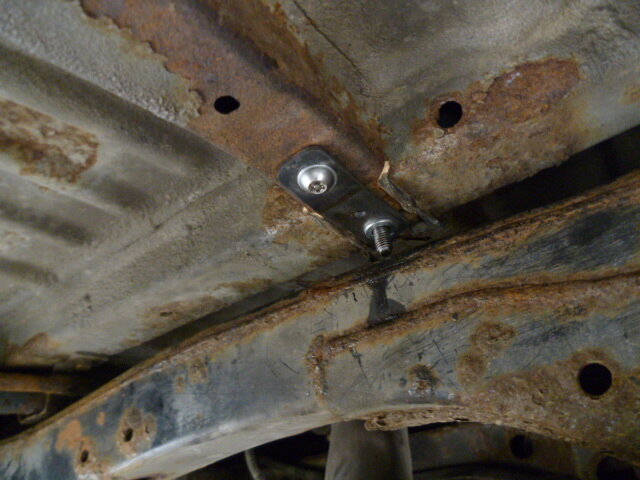
Morning Warren. That's fine. Yes, there are different sized nut bodies. But I can't recall how big my holes were. I just picked a nut that fitted. I see now why on the other threads on this, people cut out a piece of the box so that they can got inside to bolt through, then weld the chassis back up again! As an import, I am surprised it doesn't have the threads in there. I got to the point where the hole got a bit bashed up, so you'll see that I made a little plate to reinforce the hole. I then had to fit a stud in it which was thread locked in there. It was a real faff.


P1010552.JPG
 
Don't like the adverts?  Click here to remove them
Finally caught up on your thread Chris. :thumbup:

Some excellent work going into the build as always! :clap:
 
Cheers Ben, although I rather think I shall have finished the build before I get anywhere near the thousand pages you have built up. If a certain someone would pull their finger out and get me these new slinky springs, I'd be a couple of posts away from it being done.
 
Chris
love the sight gauge bit open for breakage but its not mine.....

real question time did you think about your COG when the water tank was placed as high up in the crusier? or does it not really matter as there is a roof full of heavy stuff.

stu
 
Stu, remember it's countered by the additional fuel load down below mate. See I think about this stuff.

If the vehicle is destabalised by putting 60 kg of water in there what happens when a normal cruiser gets 5 adults and 3 kids in it?

Think I'll be alright.
 
thanks chris
I was just thinking about my own lay out and was something that i was pondering for a while.

good way to think about it. i was thinking if people put 5-10 jerry cans on the roof it would be ok for a water tank in the back above a drawer

stu
 
And if you think about my track, I am running steels with a total -60 off set. Now I am not capable of doing the maths but that makes a difference too, being wider.
 
Had an odd one with the window motor on the driver's side. For some reason the limit stopped working and it just kept winding till it was bust. So, I set out to try and sort that out today. Blimey, that turned into a day's work. OK long boring story but in the end, I made Frankenmotor. I must have stripped 4 motors for parts to find the best. I ended up combing the spindle and armature from one, different brushes, large ring gear, pinion and even the outer cover off another. The result is a decent window motor. But I did learn something which is the long winded point of this post.

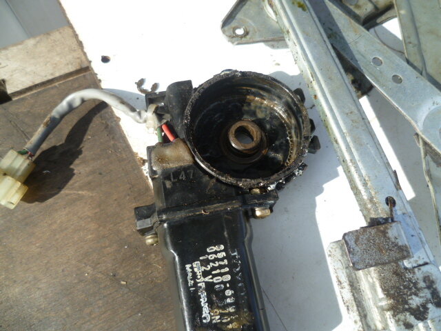
Here's the inside of the body. It seems that in the main, this bit lasts well. One of the motors had no brushes left and the commutator was utterly bald! How many window actuations did that have!

Body.JPG

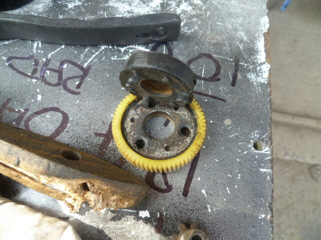
Now the ring gear is in two parts really. There is the gear itself driven by the worm gear and then the drive transfer part that turns the spur gear. I didn't realise to start with but there are two types. Essentially this bit is a flexible joint, presumably to take shock loading on the mechanism. The older design has the two halves bonded together and the later system has it in two separate halves that lock together.

New one with metal lugs that engage with the drive gear

Old ring gear.JPG

This is the older design with a sort of RTV bond to mate the two halves. Really they are just glued together.

New ring gear 2.JPG


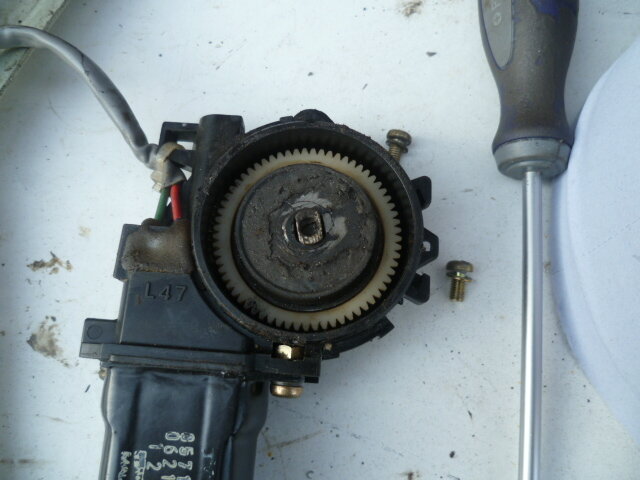
You can see the reason that the motors go all "Wobbly Bob' on you. Look at the key hole that develops in the drive transfer plate. I tries to weld that up and mill it back out again. Well that was an hour wasted. Jeez.

Central wear.JPG

This back end slop allows the spur gear to weather vane around and that resulting yaw jams the window regulator and even allows it to skip teeth. I think that you could do some cleaning up and then just spot weld the top of the spindle to the drive plate actually. Another story I think. Anyway....

Assembled.JPG

Stuck all the best bits back together and away we go.

OK so go on thent, what's the point of all this. Well, motors are expensive and they do cause issues when they wear. But, there are repair options. Strip and clean, reassemble and spot weld the sloppy bit. Or get a bucket of spares and spend all day fannying around looking for the best bits.
 
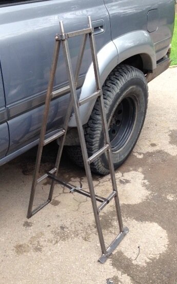
Ok so here's the thing. RTTs are great but pretty high up and once you have a nice fancy set of suspenders on the car and chunko wheels, it's along way up. Side steps are very useful in helping to reach your airborne goodies I have to say, but unless you have been snoozing on the dark side of Venus, you will know that I haven't gotten around to making those yet. The GS doesn't come with steps as standard. I have been using an aluminium loft ladder to get up top until now and whilst perfectly effective is a pain in the ass to store. So..... Oh you're ahead of me..

Yep, I have made set of custom step. Now the story here is that I made a two piece ladder actually, but being no stranger to Mrs Miggin's Pie Emporium, it did bend a bit when I stood in the middle. Then today 'Shazaam' it hit me. Let's turn them into step ladders. By the magic of the interweb.. here's some I made earlier.

Ladder 1.jpg


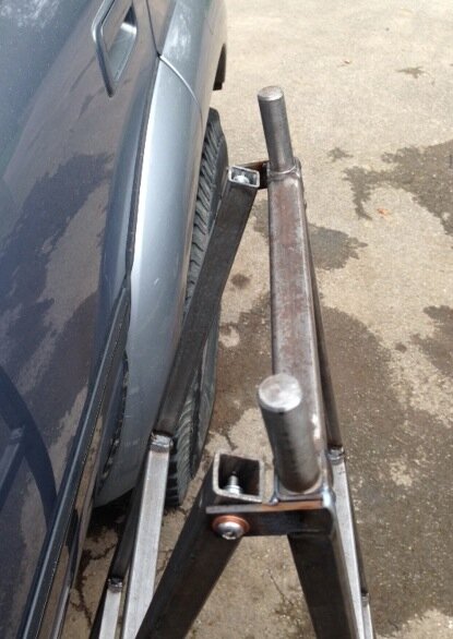
They actually fit under the roof rack, or inside but are best stowed between the roof box and the RTT. Cute thing is that they can be split and pushed together to form one long ladder or, and this is neat, used as ramps or bridging ladders if supported with rocks, earth, small children etc. I'm stoked I tell yah.

Joint.jpg

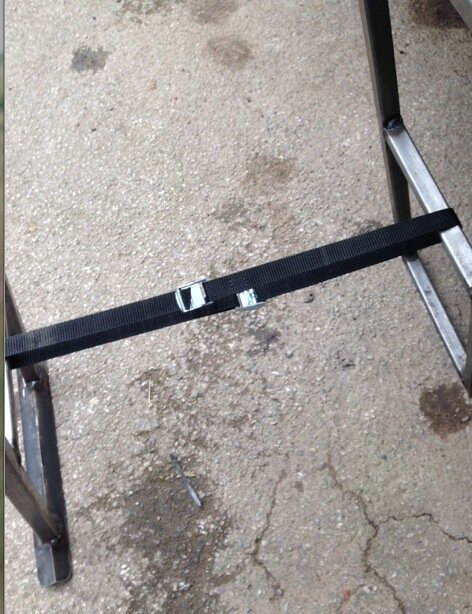
OK you can only get one foot in each rung, but they work. You can straddle them too and are very stable. So plan is to get them galvanised locally and put them on the roof. There are two canoe straps that hold them in place which can be joined together to make a check strap.

Check strap.jpg

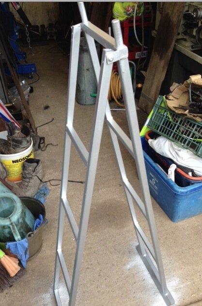
For now I have cold galv sprayed them

Bling.

Rattle can.jpg

Sorted.
 
I like them Chris, are they very heavy?

I can't even clean my windscreen without some climbing gear, but I do have the advantage of the barn type doors on the back of my truck that allowed me to put a fixed ladder on the driver's side, adjacent the swing out spare carrier. It's a bit of a hoik up to the bumper as the bottom rung, unlike your's which starts at ground level.

(I give up trying to upload a pic, I'm on hotel steam driven wifi bugger, bugger:angry-screaming:)


Nice work, they will look cool after galv. :thumbup:
 
Last edited:
Neat idea Chris.

looking at the design they look like they could twist all the way up and make a normal ladder anyway?
 
Nice work as always Chris. :thumbup:

One minor point - would they not benefit from 4 small "feet" - say 1" or so? The current set-up is great if on even ground but if it's uneven or there is any give in the surface would they be as steady?

Just a thought - I'm certainly no expert on ladders (or anything much else for that matter)! :icon-wink:
 
but I do have the advantage of the barn type doors on the back of my truck that allowed me to put a fixed ladder on the driver's side, adjacent the swing out spare carrier. It's a bit of a hook up to the bumper as the bottom rung, unlike your's which starts at ground level.
A ladder can be fixed to the upper tailgate. I got fed up with a separate ladder taking up space, (I know they can be stowed somewhere) but this saves me have to drag it out and extend it, hook it onto the RTT and then have to put it away again when striking camp, I realise the tent can't be accessed with the tailgate up but when going to bed everything is closed up anyway, this is altogether more convenient.

Sorry but I can't find a closer pic.

5.jpg
 
Chas, I have a RTT not a pop up so rear ladder utterly useless for me.

Chad, good point, remind me to only ever park on level ground.

Karl, I know what you mean but not quite. Shame but the strength in the joint is crucial. They really need to lock together.

Clive, yes they are. Put them on a weighbridge and the steps alone came to 63, 000 kgs.

No. They aren't heavy.
 
YYY
Back
Top