Don't like the adverts?  Click here to remove them

Project 80: Codename Grey Ghost

Ahh, in that case Stu, I don't quite follow your plan. You need a shaft that doesn't move and a shroud that does. The shaft has roller taper bearings on it top and bottom. Not clear on which bit you'd substitute to make it quicker. Making the shroud bit is actually very easy and quick. The time is in removing excess metal off the shaft pass after pass after pass. Do you mean that slot in replacement wheel bearings that come in a tube? Our Corolla has those. Throw away unit. That wouldn't save me any time really and as the last one I bought was £60 it wouldn't be viable. It would work in principle that yes. But you'd have to pull the bearings out when you came to weld it.

Worth thinking on though. But like I said, it's the shaft machining that's the time consuming bit which you'd still have to do. Unless you could get the stub axle too and weld that straight onto the bumper. You get tremendous flex even in things that look solid. The leverage effect is huge. The best way is to g through both planes of the bumper for sure. The hub one I made has been good actually, I didn't shut it properly and reversed it in a tree several times without realising. That's why it bent. It was the pin, not the mount at all. Just the pin. We put the tyre on, I climbed up on top and bounced up and down until it was straight again. Pin possibly a bit soft.

Chris
 
Chris

this is the type I was thinking of.
Its hard to explain with out a drawing what I am thinking of and I don't have a scanner to put the picture here.
you can get these for not a lot of money.
timkin do one that is 44mm id and something like 68mm od and they are about £35 ea

images?q=tbn:ANd9GcQntomc1DPpNBMPcY4hb-8oNbDv-pCc29OStDvxHii1911ombJ4.jpg
 
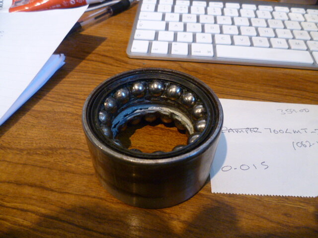
Yep, I know what you mean. Not sure it works quite as well though. These bearings are held captive in there and support the wheel of course, but in essence I think that they are pre set. The nut just stops them coming off the shaft, but from memory they are not taper bearings they are ball races so you can't nip them up. The shaft is one diameter all the way up. Tightening the nut doesn't tighten the pre load. I have one in my garage and it wasn't easy to get to bits without damage and all the balls fell out. If it worked Stu, and I got some stock that was nearly to size, yes it would save a whole load of machining. Just not sure it would work necessarily. it would have to be very accurately machined which takes time. With the taper bearings, it's not as critical as the slack is taken up by the tightening of the top nut. The top bearing on mine is free flaoting up and down the shaft you see. These bearings in that sealed unit can't move any closer to each other. I'm not explaining that very well, but I can see it in my mind. It could work, I am not dismissing that in any way. I just think that it creates new issues as it resolves others. Not sure it's deep enough either for the arm You also need find a way of putting a cap on the top.
 
In fact here it is. It was behind me.

P1010312.JPG
 
The bearing i have seen has Rollers not ball on a nice angle.
I do see what you mean about the adjustment with regard to the pair of tapered bearings.
I wasnt thinking of using a cap as these are meant to be so well sealed.

Do you need preload on them? I suppose with nothing there when you open the arm off the mount it would drop until the slack in the bearing is taken up which would annoy me.
I know that this method has been proven to instead of reinventing the wheel might just use the tapers. Are the sealed tapers better ? not sure how well they would seal.
What size is the shaft to atart with

stu
 
Stu, not even sealed bearings are 100% really sealed. The one I get are shielded bearings I guess not sealed. But as the cap is sealed, water can't get down into them. Plus you grease 'em up good. Well prelaod isn't necessary in relation to the friction of opening although it helps, but you need the spindle to have the same movement in it loaded as unloaded so that when you shut it, all the locking etc lines up. When it's closed and locked the forces at work are under control, but when it's opened and all the weight drops onto the pin it's a different matter. It needs to be engineered for those moments when it swings open one day when you don't lock it! I did this once and the hold open pin engaged to lock it open and the combined weight just snipped it off clean. 10mm steel pin.
 
Don't like the adverts?  Click here to remove them
looks like a lot of work done by yourself! To bad that i cant do such stuff by myself :-(
 
Chris - do you have any photos showing how the drawer top the fridge is attached to is latched to keep it shut.
the main drawers have obvious latches, but i am not sure about the upper fridge drawer!?

cheers
Andy
 
Those bearings seem expensive Stu if you'll still need 2 of them which I think you would?
 
you would only need 1 bearing per side. if you were paying somebody to do the machining it might save you money in the long run. i can get a pair made for my self for free but would need to pay to get any more made up.
stu
 
Andy, I don't but I will get you some tomorrow. Basically it's a very simple little lever that gets pushed up when you close the drawer. This locks the sliding top. When you want to pull the fridge out, you have to 'crack' the drawer underneath. This is in part why I have put the slider on as well so that on a slope you don't get flattened by the drawer when getting into the fridge.
 
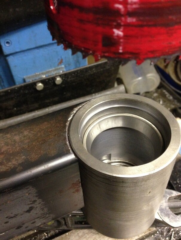
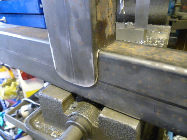
Right, enough about bloody bearings. I think that needs another thread. Moving on. Got some workshop time tonight and started bits for the carrier. Not much worth seeing but cut the end profile on the arm where it meets the shroud. Have to say that the hole saw was shite. first contact it threw 4 teeth! It cut well enough, but that's rubbish. I have hole saws that have done dozens of cuts. This was on the miller with coolant slow speed and feed. Bang, teeth gone. But, oh my, it couldn't have been any closer. That's a heck of a fit is that. You'll barely see a join. At the same time I had a whole (no pun) new idea on the hold open latch. Man can't wait to do that. And the main locking pin too. Proper light bulb moment. But you'll have to wait for that.

Trust me it's gong to be great.

Screen Shot 2013-12-09 at 21.58.57.jpg
 
As chuffed as a squirrel finding a 2 for 1 offer on hazelnuts in Tesco. Some new milling cutter arrived today. Like a laser through fog, I can tell you.

So what have we been up to this evening..

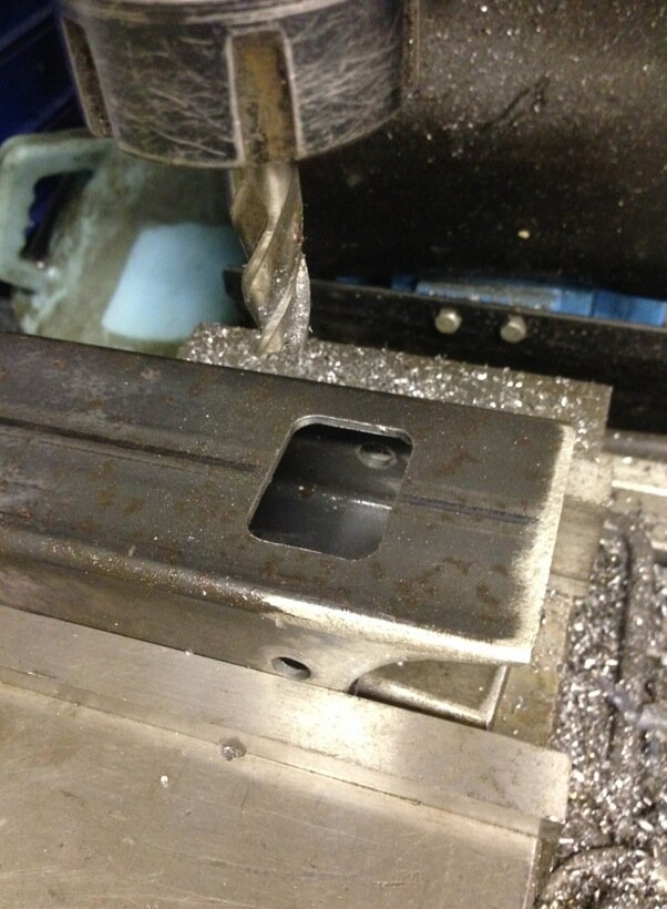
Bit of milling action first

Screen Shot 2013-12-11 at 20.13.00.jpg

Hmm, what's that for?

Screen Shot 2013-12-11 at 20.13.25.jpg

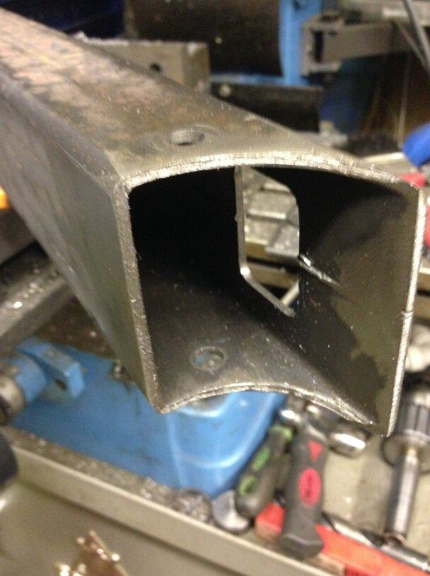
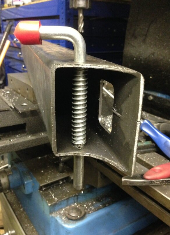
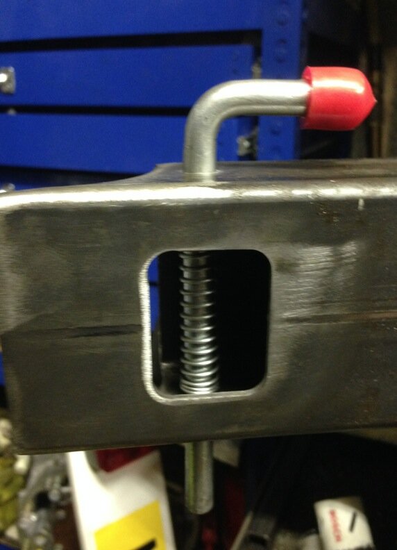
Ahhhh, a hold open latch for the carrier arm, inside the arm

Screen Shot 2013-12-11 at 20.13.43.jpg

And the hatch - for installation, repair and maintenance. Plastic cap will push in there once powder coated

Screen Shot 2013-12-11 at 20.13.56.jpg

Yep. I like that and the same at the other end only bigger for the locking catch.
 
Nice bit of milling and another interesting idea to file away :icon-cool:
 
Very nice - but then again, exactly what we've come to expect! :icon-cool:
 
Thanks chaps. Thought you might like that Jon. New cutters - ooh. also sorted the DRO on the y axis. Was worried but all it was, was the two screws holding the scale onto the side of the miller base. Went to undo them and they practically fell out! All that jiggling in the trailer must have loosened them. Spot on now.
 
With all your pics Chris it really puts it into perspective why these items cost so much to buy! Given the size of the spindle you've built they probably aren't as robust though. Great work :)
 
Right, time for today's thrilling instalment. Just got time before 'Strikly' is on the telly. I like to put it on while I go out.

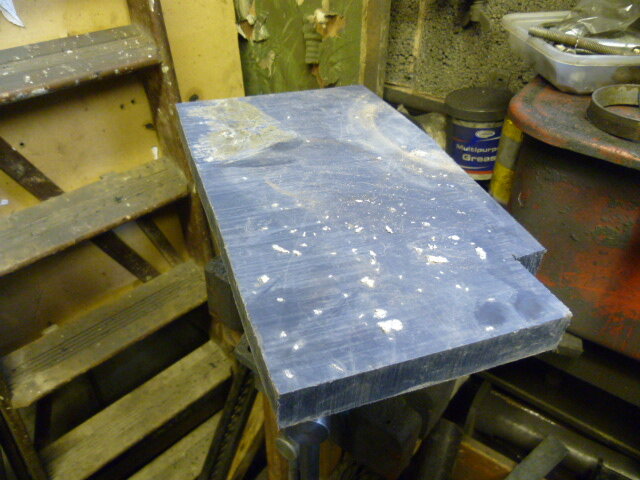
Started the morning with a lump of this.

P1010318.JPG

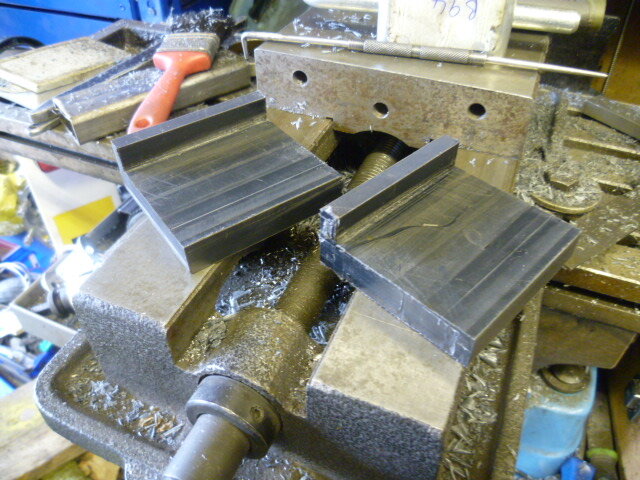
Milled them into two lumps like this.

P1010319.JPG

These are the arm retainers in which the arm will sit when closed. I may not put two on, I shall wait and see. They will get bevelled front edges to le the arm ride up if it droops at all, but not planning on that happening with the monster pin that I used.

The locking pin, when it goes in, will likewise lock through this block into the bumper. I shall make it adjustable to take up any rattle. Used this idea before and it worked very well.

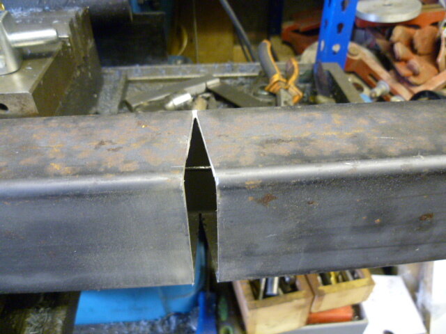
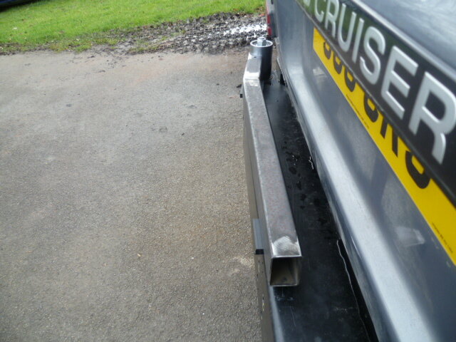
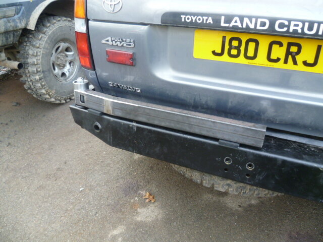
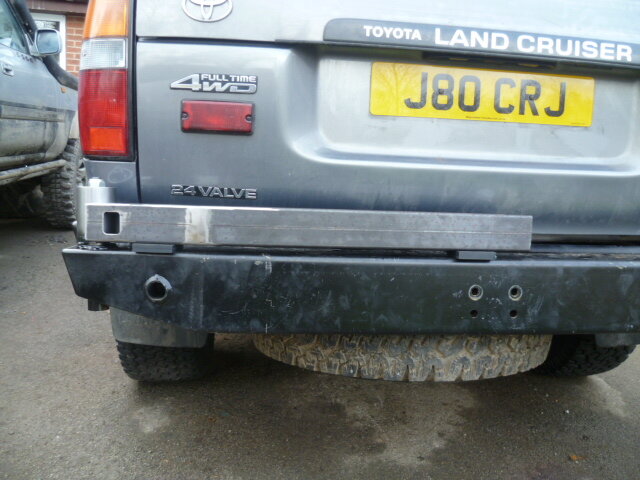
Put a kick in the arm to bring it flush with the leading edge of the bumper

P1010321.JPG


P1010323.JPG

P1010322.JPG


Looking at the pin, yes, the arm is low down on the shroud. Each mm higher creates more potential bending moment in the pin. So I want it low down. It's a bit of poor planning really as it's too late to re machine the pin and shroud. I knew it was all going too well.

P1010324.JPG

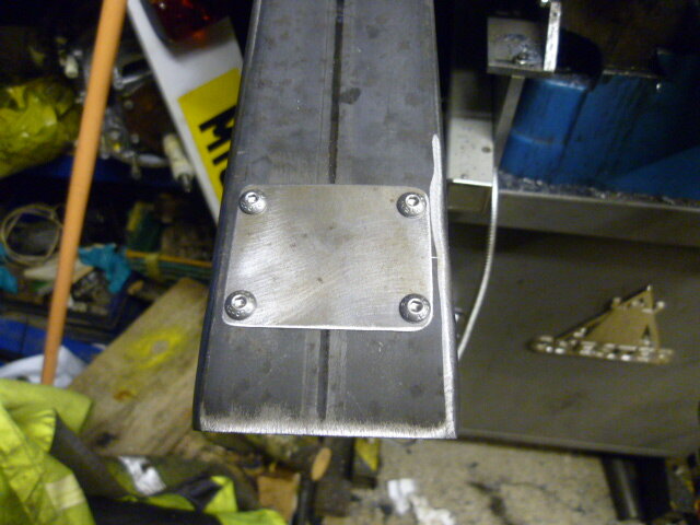
And made a little cover plate for the access hole to the hold open pin

P1010327.JPG

Also made a start on the main support arm for the carrier section

P1010325.JPG

I like to use these overlapping joints rather than butt welds. It increases the weld are substantially. Given all that bouncing up and down, you can't beat having a nice stiff one. :icon-eek:
This will be on the back side of the arm where the bending moment will be most pronounced. I have never had a spare fall off and an inch of weld holds a tonne. But as I said before, I am going for fail-safe on this build.


Whaddya mean is that all you've done!!!!
 
Back
Top